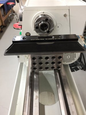
Setting-up the PM 1236-T Lathe

Thinking about the differences in our lathes, I have the 1440GS from PM got me wondering why I couldnt do something very similar yet a bit different. I thought about getting a couple of plates made up, 1" thick (I have a friend that has a fabrication shop and they can cut up to 3" thick steel among their many toys). Not sure why I couldnt use a similar approach where I put the PM leveling pads that I got with my lathe on the 1" steel plates with 4 casters each. The 1440GS weighs 1800 pounds. I put a carpenters level down on the floor and the floor forward and backwards (to the wall and away from the wall) is fairly consistent in terms of levelness. I think I would be concerned about the lathe "walking off the steel plates" if the floor wasnt fairly sloped the same. Your thoughts on my thoughts and my approach?
 
now I understand, you level the lathe to the base and the base has the casters that you lift off the ground with the outrigger jack screws when you park it. I was missing the rest of the story but I see it now. All is good!

Firstgear, it sounds like you have it correct but I want to make sure. One point I don’t think I made clear is that the baseplate does not need to be level to the stand. Let me just briefly go over the leveling process:

1.) place the precision level, or whatever level you have access to, on the ways at the headstock end. Use the leveling foot of the caster to center the bubble on the level. The stand does not need to be particularly level, only the precision level needs to be level.

2.) move the level toward the tailstock at marked intervals recording the position of the bubble on the marks of the level as you go.

3.) once you reach the last mark at the tailstock end decide whether the tailstock is a bit high or a bit low toward the operator and make the appropriate adjustment of the jack screws to raise or lower the appropriate side of the tailstock. Use very small changes here. Minute changes are all that are needed. Sometimes just tightening or loosening the nut on the anchor bolts is enough to make the difference you need.

4.) go back to the starting point and check the level. It most likely will not be in the middle any longer. Even though the change was made at the tailstock end it will almost certainly affect the reading near the headstock, so you need to re-zero the precision level again using the leveling foot of the caster, then work your way down toward the tailstock taking readings again, make and adjustment with the tailstock jack screw and start all over until you are satisfied. It took me eight times to get it where I wanted it.

I hope this helps
 
Have you done or do you plan to do a 2-collar test to finalize your settings?
 
Thinking about the differences in our lathes, I have the 1440GS from PM got me wondering why I couldnt do something very similar yet a bit different. I thought about getting a couple of plates made up, 1" thick (I have a friend that has a fabrication shop and they can cut up to 3" thick steel among their many toys). Not sure why I couldnt use a similar approach where I put the PM leveling pads that I got with my lathe on the 1" steel plates with 4 casters each. The 1440GS weighs 1800 pounds. I put a carpenters level down on the floor and the floor forward and backwards (to the wall and away from the wall) is fairly consistent in terms of levelness. I think I would be concerned about the lathe "walking off the steel plates" if the floor wasnt fairly sloped the same. Your thoughts on my thoughts and my approach?

Firstgear, I am not sure what you have in mind. It sounds like you are thinking of having one plate under the base of each pedestal of your stand?
 
As with others, I am watching with interest at how this build goes. My 1340GT headstock base had a crown that allowed it to flex - bump the lathe and it would wiggle for awhile. I welded a 3/8" plate inside, with vertical reinforceing ribs to tie everything together. Obviously, I was in the "tie it to the ground " camp - based on where I work. My questions have been asked and answered, the proof will be known soon. As Bruce said, you didn't know better and came up with a thoughtful alternative. As I think about this, you look at old lathes with their elegant, but relatively unsubstantial, legs, this solution isn't that far out there. One cool feature is you have not really changed anything if issues arise - the rubber isolation system could be replaced with something more solid, and your ground plate gives you a fairly flat plane to work off of. Or maybe the headstock goes solid and the tail stays like it is. From designing Diesel engine mounts, I know that the amount of preload on the bushings affects how they isolate - could be something useful while tuning things.

If this is what you come up with for a base, can't wait to see what you come up with on a real machining project. You seem to think enough and detail oriented enough that you will fit right in. Nice job, thanks.

GL, it sounds like you came up with a good solution for your base problem. All the projects listed on the initial outline of the post have been completed except for the last one on tolerances and adjustments. I have a lot planned for that so hopefully I can update you soon on how well the lathe performs.
 
“The enemy of good is better”

50223BDE-AFAF-4042-AB01-A2842A313151.jpeg

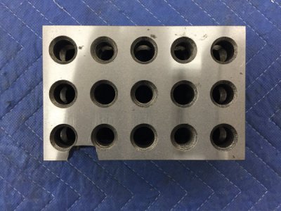
So, I used the precision lathe on the carriage to adjust the twist in the lathe to slightly less than 0.0005”/foot. But, oh no, that wasn’t good enough, so I thought I would try using a precision ground 2-4-6 block directly on the ways with the precision level. I had a cheap set so I thought I would just mill out a groove so it would straddle the v-way. Well those blocks I found out are ground and HARDENED so I ruined an end mill finding that out. But I really wanted to try the block as well, so I put it in a vice, got the grinder out and went to work until I felt kind of warm, saw smoke, and when I looked down I saw favorite sweatshirt on fire. I think I may have my avatar for HM.

BTW, the results were the same.

72299750-FC51-48F2-928C-4C048A865090.jpeg. 048B1C19-2D1C-47B1-A139-5EA5A2806756.jpeg

Tomorrow I am going to try to find some time to present some thoughts on vertical misalignment and it’s affects on taper to finish-up this section on leveling.
 
Firstgear, I am not sure what you have in mind. It sounds like you are thinking of having one plate under the base of each pedestal of your stand?
Yes, one plate with 4 casters each, the 4 casters under each pedestal means that the plates don’t have to be attached to the lathe. The lathe only has to be level in the machining position on those plates, at least that is how I understand your approach. The lathe sits on the plates with the PM levelers. Am I simplifying this in my case?
 
Knurler, I really like your idea of a solid plate to mount your lathe to... :encourage: I'm always looking for a better way to do something!
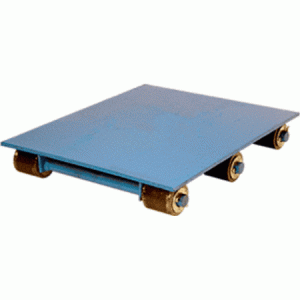
When I built my lathe stand 38 odd years ago, I couldn't afford a big plate, nor did I have the equipment to move or lift it... So I built a stand with two small 3/4" thick plates around 10" X 12", with 3" X 3/8 angle iron connecting them, The whole thing has to be leveled together - not much of a burden, and has worked well all these years.
 
Firstgear, are you about something like equipment dollies with casters instead of wheels under each column of your stand?

F550B0D4-D2BA-4C9F-99DD-58293C62C823.gif

If so, that will certainly allow you to move the lathe but they will not keep the stand from twisting and affecting the lathe adjustment. You would need to check and re-adjust with each move. I hope that helps.
 
Back
Top