2.) Machine Mounts
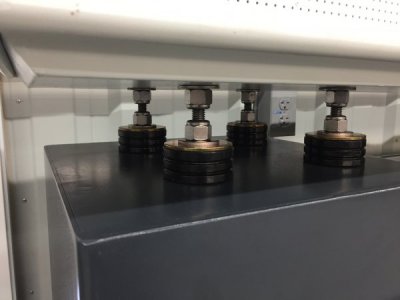
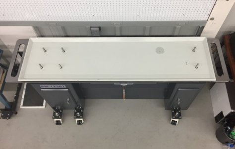
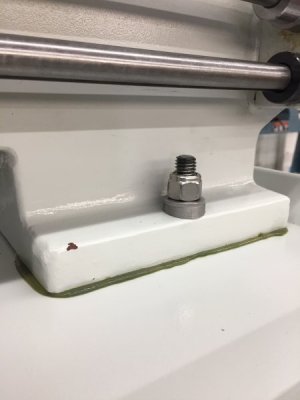
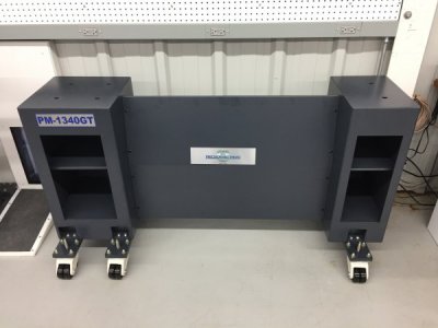
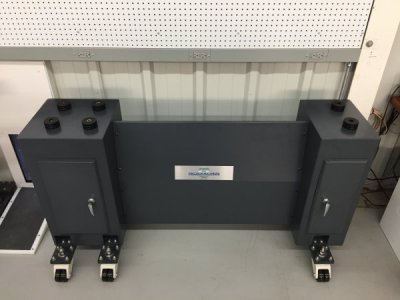
The PM stands is made of two very substantial vertical columns made of 3/16” steel plate and a heavyweight 16 gauge connecting panel that attaches to the columns by way of several small screws to a piece of angle iron welded to the side of each column.
.
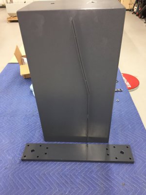
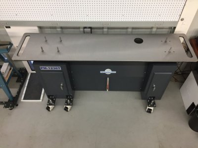
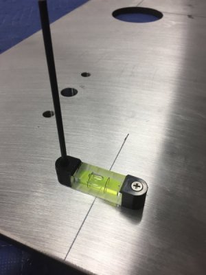
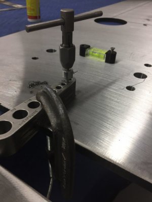
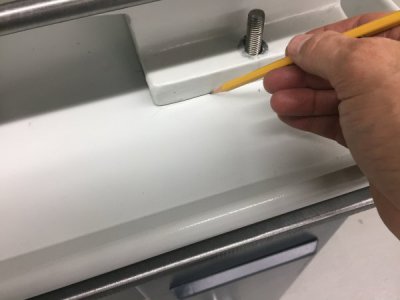
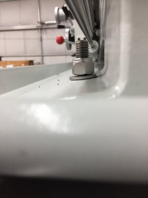
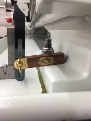
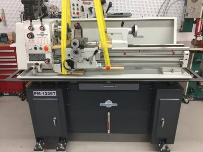
The components are all heavy duty but when they are bolted together there is a fair amount of movement of the columns especially in the vertical axis. In fact, when I was trying to carefully mark the positions of the mounting holes for the lathe on the top of the assembled cabinet I had to use a bar clamp, with the ends reversed, to counter the toe-in of the columns. I imagine when the cabinet is used as intended, as a stationary base with the lathe bolted directly to it, the stand is plenty rigid, however, I don’t think it is rigid enough to be used as a mobile base without a baseplate. Something more rigid, such as a cast iron base, might provide the rigidity needed for a mobile base without modification.
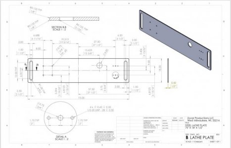
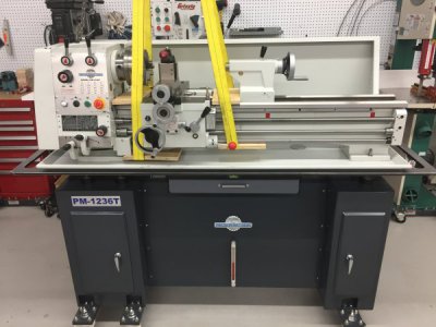
Because of the movement of the stand I used a baseplate to provide a stable mount for the lathe. The equipment mounts help mitigate the effects the movement of the stand on the plate; when the stand flexes and twists the rubber mounts will absorb this force.
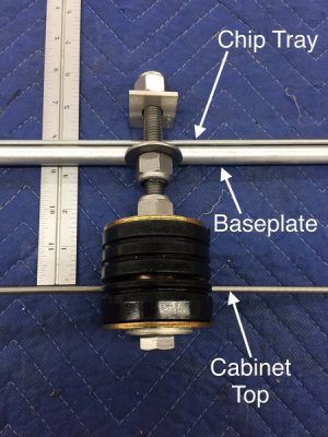
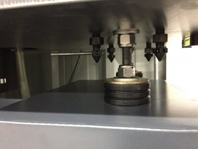
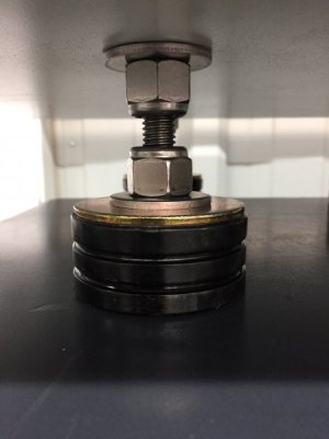
The above is a labeled mock-up view of a mount, it’s hardware and the relative positions of the cabinet top, baseplate and chip tray. If you envision that this is just one corner of the mobile stand I think you can visualize how the mounts help reduce the forces of a moving stand on the baseplate. If while moving the stand a corner drops, say it passes over a drain in the floor, the lower pad will compress and the upper pad will expand until the ability of the pads to compress or expand is exceeded then the force will be applied to the baseplate. It is like you have a spring above and below to absorb the forces. I doubt this arrangement eliminates all forces on the baseplate from a moving and twisting stand but I do think it minimizes them and is better than mounting the baseplate directly to a shifting stand. This elevated arrangement also allowed me to easily access the jack screws for leveling that are on the tailstock end of the baseplate and to place a drawer under the baseplate. You might be asking yourself if this elevated arrangement may cause increased vibration of the lathe? I will answer this question later with some vibration measurements once the lathe is attached to the stand.
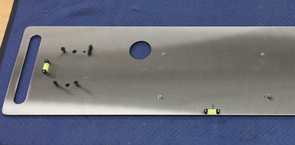
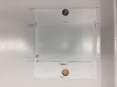
To use the equipment mounts I had to enlarge the small oval holes to on the top of the stand to 1-1/4” so they would accept the equipment mounts. If any of you have ever tried to use a hole saw to enlarge an existing hole that is larger than the pilot bit you know it can be tricky. I clamped a board on the backside and used the drill press; this seemed to do the trick.
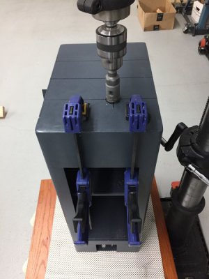
.
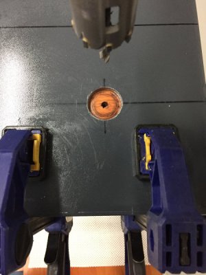
This view shows the mounts in place ready for the hardware:
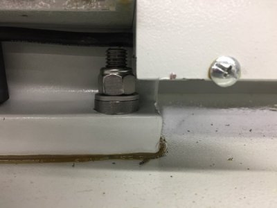
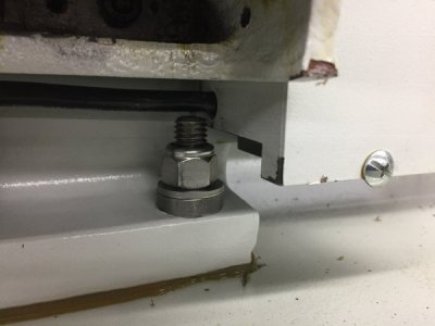
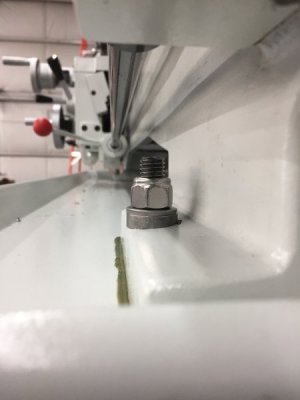
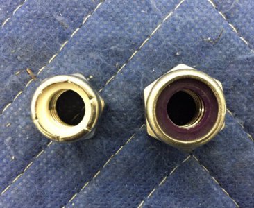
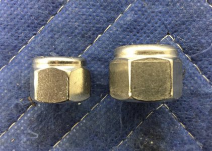
I used eight inch 1/2”-13, 316 stainless bolts and oversized locknuts And heavy duty fender washers:
.
Here is a mount that has been installed:
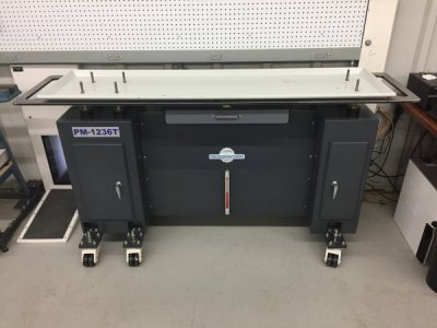
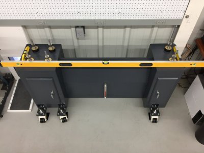
This last view show the stand columns leveled and the mounts installed and ready to accept the baseplate, chip tray and finally the lathe:
Well, that’s it for the equipment mounts. Now on to the last component of the mobile stand, the baseplate.


