- Joined
- Jan 18, 2018
- Messages
- 314
I apologize, for some reason a diagram and a photo did not show up in the last post. You can only see, “view attachment 288059” and “view attachment 288158”. I will attempt to cut and post the last post and insert them. Hope it works, sorry about that, pretty frustrating.
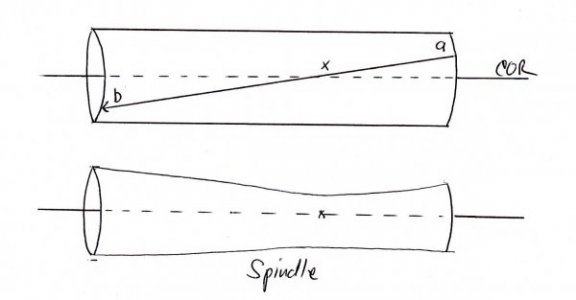
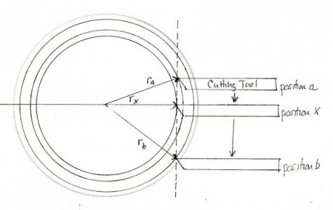
Why get rid of the twist in the Ways? One reason is that a twist in the lathe bed or Ways will cause the cutting tool to rise or fall from it’s starting height as the carriage travels down the Ways. Since the workpiece is round, as the tool rises or falls from the center of rotation(COR) the tool will remove less from the workpiece causing a taper, or if the cutting tool starts above or below the COR and then crosses the COR a spindle shape will occur with the thinnest spot, or waist, at the point the tool crosses the COR. So, not only might you have an undesirable uniform taper formed but you could also have a part whose diameter does not vary linearly along its length. Here are some diagrams I showed earlier that illustrate the effects of a rising or falling tool:

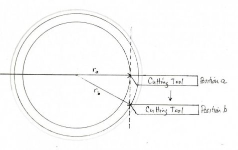

In the above diagrams the tool starts at height “a”(the COR) and descends along the Ways to point “b”, removing less stock as it travels resulting in a uniform taper. This is also true if you start at “b” and go to “a” or if the tool ascends or descends.
In the diagrams below the tool again starts at point “a” but this time it is above the COR, it descends as it travels down the Ways and crosses the COR at point “x” where it removes the most stock. This results in a spindle shape with the thinnest spot at point “x”:

So, the first reason for untwisting the Ways is to prevent taper and spindle formation.
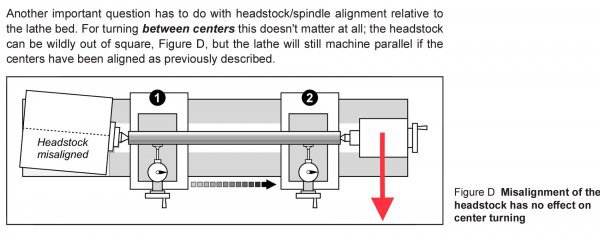
The second reason for untwisting the Ways early-on in the alignment process is so that you can accurately adjust the Headstock and Tailstock. For example, if you try to align the Headstock or Tailstock before untwisting the Ways by using a dial indicator or performing a two collar test you might find taper that is attributable to twisted Ways and incorrectly assume it is from a misaligned Headstock or Tailstock and make unnecessary and incorrect adjustments of the direction of the Headstock or the position of the Tailstock. By the way, this is one of the reasons you will see in the upcoming sections that I used a dial indicator with a ground flat tip rather than a spherical tip. If there is any residual twist in the Ways the ground flat tip will minimize any error that might be introduced by a spherical tip riding up or down the test rod as you you move down the Ways indicating taper where there is none.
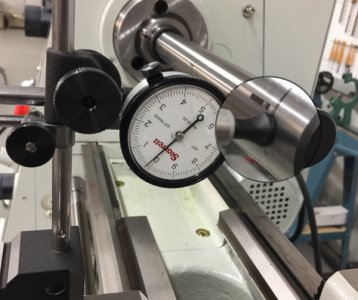
So, to make a long story short, the reason for untwisting the lathe bed prior to aligning the Headstock and Tailstock is to get rid of any taper that could be mistakenly attributed to Headstock or Tailstock misalignment.
So how does one untwist the lathe bed? The first thing is to make sure you are in the right frame of mind; make sure you have plenty of time to carefully make repeat adjustments; often very small adjustments. If you have mounted your lathe in the conventional way, that is, directly to the stand, the steps are as follows:
If you have mounted the lathe on a plate with jack screws, like I have done, then the process is similar except that it is a bit easier since one can make adjustments quickly with the jack screws, rather than using shims, and the adjustments made using the leveling bolts to re-level the stand at the Headstock will not affect the lathe twist. This is because the lathe/baseplate unit is unaffected by the adjustments of the stand leveling bolts. Here are my results:

As you can see It took eight tries to get it where I wanted but I did go back later and was able to reduce the twist to zero according to the precision level. It is a tedious process but now I can proceed to the next steps confident that any taper I find is not due to twisted Ways.
Aside: since I am still waiting on supplies to complete the following sections I thought I would torture you with putting a finer point on Dr Jackson’s formula for determining the change in the depth of cut caused by a tool dropping or rising due to twisted Ways. If you recall he determined that:
Change in the depth of cut = (Distance the tool drops x Distance the tool drops)
(2 x Radius of the Workpiece)
Since (2 x Radius) = Diameter, the formula can be re-written to:
Change in the depth of cut = (Distance the tool drops x Distance the tool drops)
Diameter of the Workpiece
What kind of taper would I have found with the lathe prior to untwisting it? If you look at the chart above, the out-of-the-box twist for my 1236-T was 4.5 lines of twist on the precision level. Each line represents .0005”drop/ foot. So, 4.5 x .0005”=0.0023”drop/foot. The lathe bed is three feet long so the total drop in the tool height would be 3 x 0.0023”=0.0069” over the length of the bed. Now, if we use Dr Jackson’s formula the change in the depth of cut over three feet for a workpiece with a diameter of 1” will be: (0.0069”x 0.0069”)/ 1”=0.00048”. That is about a half a thousandth of taper over three feet. Not much, and I think it is probably even less than what Dr Jackson’s formula predicts. Why do I think it is less? Well, if you look at the photo of the twisted rails at the end of the last post you can see that when the right rail is lifted up not only does it go up but since it is tied to the other rail(as are the rails of the lathe) it moves to the left or toward the other rail as well. If the right rail is analogous to the front rail on the lathe then as the front rail is lifted it moves inward toward the workpiece and would decrease the loss of depth of cut that a tool that is simply moving upward would experience.
Well, is all of this worth a half a thousandth over three feet? Is it all much ado about nothing? 0.00048” taper over three feet is not nothing but it’s darn close. I will let you decide if it is worth it. However, I can at least move to the next steps, Aligning the Headstock with the Ways and Aligning the Tailstock with the Headstock, knowing that any taper that I find is not due to a twisted lathe bed. Surely, that’s worth something.
Which step should be done next, Aligning the Headstock to the Ways or Aligning the Tailstock to the Headstock? I believe aligning the Headstock next makes the most sense and I will tell you why I think so in the next post.
Why get rid of the twist in the Ways? One reason is that a twist in the lathe bed or Ways will cause the cutting tool to rise or fall from it’s starting height as the carriage travels down the Ways. Since the workpiece is round, as the tool rises or falls from the center of rotation(COR) the tool will remove less from the workpiece causing a taper, or if the cutting tool starts above or below the COR and then crosses the COR a spindle shape will occur with the thinnest spot, or waist, at the point the tool crosses the COR. So, not only might you have an undesirable uniform taper formed but you could also have a part whose diameter does not vary linearly along its length. Here are some diagrams I showed earlier that illustrate the effects of a rising or falling tool:


In the above diagrams the tool starts at height “a”(the COR) and descends along the Ways to point “b”, removing less stock as it travels resulting in a uniform taper. This is also true if you start at “b” and go to “a” or if the tool ascends or descends.
In the diagrams below the tool again starts at point “a” but this time it is above the COR, it descends as it travels down the Ways and crosses the COR at point “x” where it removes the most stock. This results in a spindle shape with the thinnest spot at point “x”:


So, the first reason for untwisting the Ways is to prevent taper and spindle formation.
The second reason for untwisting the Ways early-on in the alignment process is so that you can accurately adjust the Headstock and Tailstock. For example, if you try to align the Headstock or Tailstock before untwisting the Ways by using a dial indicator or performing a two collar test you might find taper that is attributable to twisted Ways and incorrectly assume it is from a misaligned Headstock or Tailstock and make unnecessary and incorrect adjustments of the direction of the Headstock or the position of the Tailstock. By the way, this is one of the reasons you will see in the upcoming sections that I used a dial indicator with a ground flat tip rather than a spherical tip. If there is any residual twist in the Ways the ground flat tip will minimize any error that might be introduced by a spherical tip riding up or down the test rod as you you move down the Ways indicating taper where there is none.

So, to make a long story short, the reason for untwisting the lathe bed prior to aligning the Headstock and Tailstock is to get rid of any taper that could be mistakenly attributed to Headstock or Tailstock misalignment.
So how does one untwist the lathe bed? The first thing is to make sure you are in the right frame of mind; make sure you have plenty of time to carefully make repeat adjustments; often very small adjustments. If you have mounted your lathe in the conventional way, that is, directly to the stand, the steps are as follows:
- Place a precision level on a ground block with a notch to clear the V-Ways or the carriage and zero the level at the spindle using the leveling feet of the base.
- Carefully slide the level to half way down the Ways and take a reading, then slide all the way down to the tailstock end of the lathe and take another reading.
- Loosen the bolts securing the tailstock footing, place a shim under the low side footing, tighten down the tailstock bolts and repeat the steps until you are satisfied with the results. What you do at the Tailstock end will almost certainly affect your reading at the Headstock so you may need to re-zero the bubble in the level if goes off the scale.
If you have mounted the lathe on a plate with jack screws, like I have done, then the process is similar except that it is a bit easier since one can make adjustments quickly with the jack screws, rather than using shims, and the adjustments made using the leveling bolts to re-level the stand at the Headstock will not affect the lathe twist. This is because the lathe/baseplate unit is unaffected by the adjustments of the stand leveling bolts. Here are my results:

As you can see It took eight tries to get it where I wanted but I did go back later and was able to reduce the twist to zero according to the precision level. It is a tedious process but now I can proceed to the next steps confident that any taper I find is not due to twisted Ways.
Aside: since I am still waiting on supplies to complete the following sections I thought I would torture you with putting a finer point on Dr Jackson’s formula for determining the change in the depth of cut caused by a tool dropping or rising due to twisted Ways. If you recall he determined that:
Change in the depth of cut = (Distance the tool drops x Distance the tool drops)
(2 x Radius of the Workpiece)
Since (2 x Radius) = Diameter, the formula can be re-written to:
Change in the depth of cut = (Distance the tool drops x Distance the tool drops)
Diameter of the Workpiece
What kind of taper would I have found with the lathe prior to untwisting it? If you look at the chart above, the out-of-the-box twist for my 1236-T was 4.5 lines of twist on the precision level. Each line represents .0005”drop/ foot. So, 4.5 x .0005”=0.0023”drop/foot. The lathe bed is three feet long so the total drop in the tool height would be 3 x 0.0023”=0.0069” over the length of the bed. Now, if we use Dr Jackson’s formula the change in the depth of cut over three feet for a workpiece with a diameter of 1” will be: (0.0069”x 0.0069”)/ 1”=0.00048”. That is about a half a thousandth of taper over three feet. Not much, and I think it is probably even less than what Dr Jackson’s formula predicts. Why do I think it is less? Well, if you look at the photo of the twisted rails at the end of the last post you can see that when the right rail is lifted up not only does it go up but since it is tied to the other rail(as are the rails of the lathe) it moves to the left or toward the other rail as well. If the right rail is analogous to the front rail on the lathe then as the front rail is lifted it moves inward toward the workpiece and would decrease the loss of depth of cut that a tool that is simply moving upward would experience.
Well, is all of this worth a half a thousandth over three feet? Is it all much ado about nothing? 0.00048” taper over three feet is not nothing but it’s darn close. I will let you decide if it is worth it. However, I can at least move to the next steps, Aligning the Headstock with the Ways and Aligning the Tailstock with the Headstock, knowing that any taper that I find is not due to a twisted lathe bed. Surely, that’s worth something.
Which step should be done next, Aligning the Headstock to the Ways or Aligning the Tailstock to the Headstock? I believe aligning the Headstock next makes the most sense and I will tell you why I think so in the next post.
Last edited:


