Seneca Falls Star #30 lathe Resto-Mod

derf

Registered
Registered
Joined
Oct 3, 2015
Messages
1,010
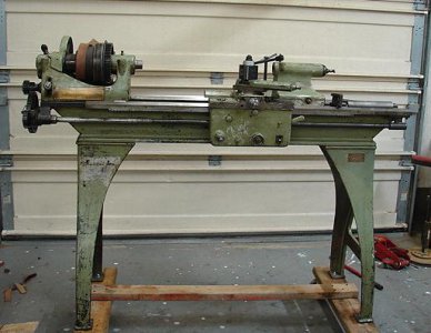
One of my buddies, and beginner machinist acquired this Seneca Falls lathe back in Sept. He was like a kid at christmas time with all the excitement of owning his first lathe. Despite the fact that it has to be 100 yrs old and in bad need of some TLC, the machine is truly very sound as far as wear. As you can see, at one time it must have been in the hills of Appalachia, where the custom drive train conversion was installed. It consisted of a Borg-Warner T-86 3 speed truck transmission, driven with a lawn sprinkler motor.
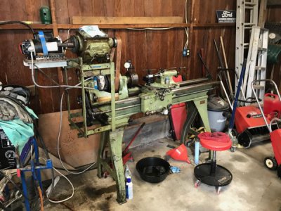
senacafallslathe.jpg

I encouraged him to buy it, for a starter machine and then realized that most of the work that it needed was past his skill level and pay grade. So I stepped up to be a mentor and took on the job of rebuilding this machine, while he helped and learned in the process. I must say, this has been fun and exciting for me as well, and I learned a few more skills. This project came to fruition last week, so I will tell the story from the time we removed the first nuts and bolts.
senecafall2.jpg
Once we removed the redneck racing speed selector, we got a better overall view of what had to be done.
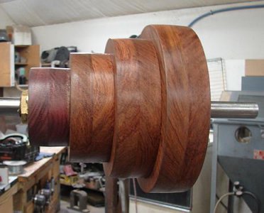
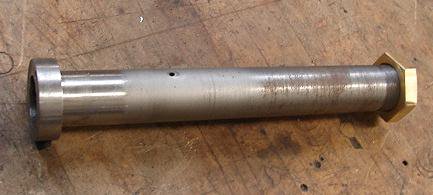
There is nothing wrong with a flat belt drive, but it would help if we woulda had the other cone pulley. Finding one of these that was compatible would be like finding unicorn tears. I came up with the idea to make a cone pulley from hardwood. I started with a sleeve to slide on to a keyed shaft, then epoxied the pulleys to the sleeve.
senecafall2.jpgpulleysleeve.jpgpulleysleeve.jpgpulleysleeve.jpgstep pulley.jpg
With that done, it gave me a better idea how to position the rest of the drive train and motor mounts.
motormt.jpg
I used some existing holes in the bed for the anchor plate.mb.jpg
Once the anchor was in place, the rest of the brackets could be positioned and tacked up.
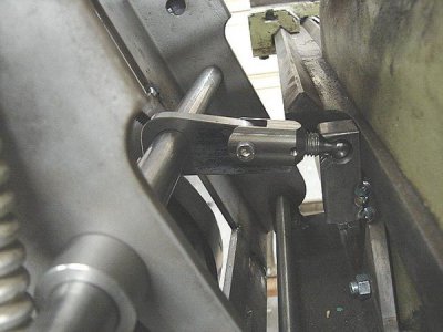
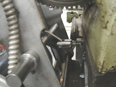
The motor/pullet bracket pivots on a 1/2" shaft, and the belt tensioner is operated with a 3/4" shaft with a simple over -center type extender with an adjustable link.
belttensioner.jpg
belttensioner2.jpg
This creates about 1" of slack to change the belt over to a different pulley.
 
One of my buddies, and beginner machinist acquired this Seneca Falls lathe back in Sept. He was like a kid at christmas time with all the excitement of owning his first lathe. Despite the fact that it has to be 100 yrs old and in bad need of some TLC, the machine is truly very sound as far as wear. As you can see, at one time it must have been in the hills of Appalachia, where the custom drive train conversion was installed. It consisted of a Borg-Warner T-86 3 speed truck transmission, driven with a lawn sprinkler motor.
View attachment 263435

I encouraged him to buy it, for a starter machine and then realized that most of the work that it needed was past his skill level and pay grade. So I stepped up to be a mentor and took on the job of rebuilding this machine, while he helped and learned in the process. I must say, this has been fun and exciting for me as well, and I learned a few more skills. This project came to fruition last week, so I will tell the story from the time we removed the first nuts and bolts.
View attachment 263440
Once we removed the redneck racing speed selector, we got a better overall view of what had to be done.
There is nothing wrong with a flat belt drive, but it would help if we woulda had the other cone pulley. Finding one of these that was compatible would be like finding unicorn tears. I came up with the idea to make a cone pulley from hardwood. I started with a sleeve to slide on to a keyed shaft, then epoxied the pulleys to the sleeve.
View attachment 263440View attachment 263441View attachment 263441View attachment 263441View attachment 263442
With that done, it gave me a better idea how to position the rest of the drive train and motor mounts.
View attachment 263443
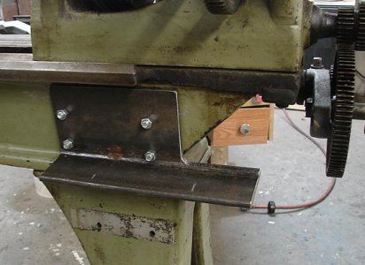
I used some existing holes in the bed for the anchor plate.View attachment 263444
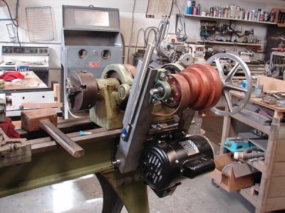
Once the anchor was in place, the rest of the brackets could be positioned and tacked up.
The motor/pullet bracket pivots on a 1/2" shaft, and the belt tensioner is operated with a 3/4" shaft with a simple over -center type extender with an adjustable link.
View attachment 263445
View attachment 263446
This creates about 1" of slack to change the belt over to a different pulley.
 
@derf,

It's great that you got the original legs with the lathe.
What size (hp) motor did you mount?
For some perspective, what size is that chuck?

Thanks for sharing this, I am "Watching" this thread!

-brino
 
Very nice job! I once made a cone pulley in that fashion for a speed lathe; there is a diagrammatic method for determining the sizes of the steps where it is all laid out full size and a straightedge used to project from one pulley to the to - be - determined pulley to be created; this assures that the belt will have equal tension on all the steps, even if one of the pulleys has larger diameter steps than the other, as the older Hendey lathes do. I found this method in one of the older machinist's handbooks, likely American Machinist's Handbook or an older Machinery's Handbook.
 
Looks good! I had a Seneca Falls lathe about 50 years ago? The one thing that stands out and I will tell you is: Check the head stock babbitt bearings. AND check the end shake and then check it again. Mine had some kind of fiber washer on the end of the rear bearing. Maybe try making a Delrin washer? I still have the taper attachment from it somewhere in the shop???...Dave
 
When I made the pulleys, I just duplicated the sizes on the spindle. The motor we used was a "donation" from a mutual friend of ours, and is a 1 hp Harbor Freight.
This headstock does not have babbit bearings....it's just cast iron. It has ring oilers that picks up oil and rolls it to the top of the spindle journal, and as it disperses it eventually ends up back into the reservoir.
The chuck is a 6" version that will be replaced in the future. The lathe is a 12" swing with a 5 ft bed. There seems to be little information about this lathe, as I have seen mentions of #10's and #20's, but nothing on a #30.
 
I have no idea why there are double posts.....my mouse has been acting very wonky. I just changed it out, so we'll see what happens. Anyway...back to the story.

Once we got the motor set up, it was time to see if it would run. The leather belt that was on it, was actually sew together on the machine. The previous owner told that he had a saddle maker do that, and it was evident because the belt was made from saddle leather.

It ran, but it had that slap from the splice in the belt, and it would not quit stretching. I knew at that point it was gonna get a rubber belt. To get a continuous belt to work, the spindle and the back gear would have to be removed, which I was not crazy about. As I told my buddy, let's do this right, and do it once. If we have to go this far, we're already committed.
So I started on tearing the headstock down, the spindle was no problem, but the back gear was a little more difficult. The way it looked, it was a one shot deal from the factory because the only way it was coming out was to extract the cam from the inboard side side. To do this, I had to make a puller and drill and tap two 10-32 holes in the cam itself to pull it to the outside. The woodruff key prevented the shaft from simply being pushed out.
All the bearing surfaces looked good, which I thought was amazing for such an old machine.
DSC02409.JPG
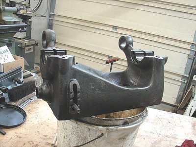
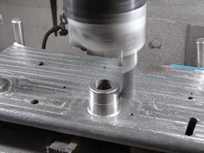
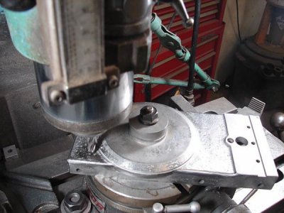
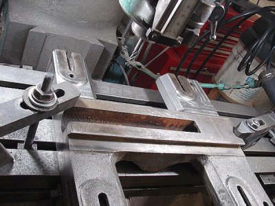
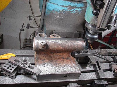
Of course the casting was rough after the 47 coats of paint and pre-Civil War crud was removed. I spent numerous hours grinding and sanding most of the scale and bumps off, and what didn't clean up got filled with bondo. A nice smooth surface cleans much easier than a rough casting, so at this point I was committed to slick up the whole top side. The saddle, apron , cross slide, tailstock and compound got the same treatment. The apron was rough enough that I decided that milling it was easier that trying to grind out unsightly blemishes.
DSC02419.JPG
Same deal on the cross slide.
DSC02417.JPG
It took a little more work on the saddle.
DSC02427.JPG
I couldn't get that detailed on the tail stock, but I got the bottom squared up.
DSC02431.JPG
I took a leveling cut on the top just to have a nice level surface to place a magnetic base for an indicator. Once all serious machining was done, I went back to the cosmetic sanding and grinding. I then spent 3 hrs cleaning up all that nasty cast iron dust from me and the machines...
 
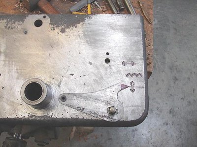
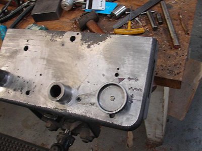
While I had the apron down, I decided a slight mod was needed to locate the position of the leadscrew/feed selector. Originally equipped with a knurled knob, it was hard to determined where the positions actually were, other than feel. I fashioned an indicator arm from 1/16" flat stock that pivots on a screw and extends out to point at the proper position.
DSC02422.JPG
Once I figured out where the true positions were, I milled in some primitive hieroglyphics to show what should be happening.
DSC02421.JPG
In case you need a translation, the horizontal line means longitudinal feed, the zig zag line means threading, the vertical line, cross feeding. ;)
 
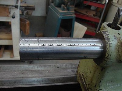
When we first got this machine moved into some good light and give it a good once over, I noticed some peculiarities that needed to be addressed. The first thing being the oddball taper in the tailstock quill. It was not quite right to be a #2 morse because the big end seated before the small end and left some wiggle. The small end of the socket was bigger than a #2, and to clean it up for a #2 was out of the question, so I bored it to a #3 on my lathe then finished up with a # 3 morse reamer. While I was at it, I set it up in the mill and cut graduations on the quill for quick reference.
DSC02412.JPG
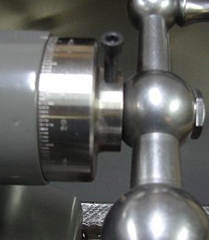
It didn't come with a dial on the crank end like most lathes of the era, so while I was on a dial binge, I made one for it. The original retainer nut had to be turned down so a hollowed out dial would fit, and it is large enough to read fairly easy.
DSC02472.JPG
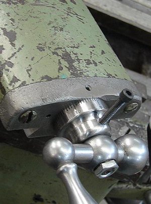
Another thing missing was a graduated dial on the compound. After I pulled the screw, it was found to be a 14 tpi, which comes out to .0714285" per revolution. So when I made the dial, I just made 72 lines and called it close enough.
DSC02411.JPG
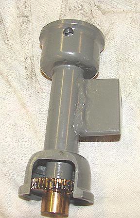
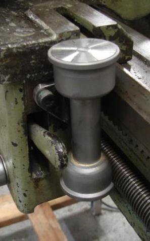
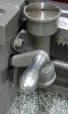
Although it was optional at the time, there was no thread dial, or a provision for mounting one. Once I figured out the gear size, I made the unit using a couple of 1" pipe caps for the flares top and bottom, and a scrap piece of barrel for the middle and brazed them together. I added the angle iron bracket and tipped it slightly so the gear meshed with the leadscrew helix.
threaddial.jpgDSC02406.JPG
It was cramped fit around the half nut lever, so a knob was added to the lever to better access.
DSC02473.JPG
 
Back
Top