rung fu clone RF-45 ZX45 cnc conversion

hi dave
the endmill was 1/2" the rpm was 670 and the feed rate was 1.9 and the depth was .030
i have an air blast nozzle that mounts to the mill this was a quicky at the end of the day as a test i didnt set up anything just placed it in the center and hit go. i use the feeds and speeds calculator in nfs wizards in mach3. so far it seems conservative but it has never damaged anything i ramp up from there.
steve
 
after hours of running I ran into a temp problem today on the controllers for x and y they will need their own cooling fans on the heat sinks, the flow moving up through the cabinet is not direct enough. there was no damage just trips an alarm light and shuts down the axis. this is also a good reason to rewire the enable circuit to the controllers in series instead so that if one controller drops out the circuit opens and shuts them all down. the way it is now only the one axis stops and the others continue to move destroying the part. if it is cutting an arc it will stop moving 1 axis giving a straight line at full depth. so i learned something from the problem not mentioned in any of the wiring diagrams i have seen. this will only work if enable drops out in an alarm but i will try it. there are no tech sheets for these controllers i even tried the manufacturer. there probably are but they are in chinese
steve
 
Last edited:
Hi Steve,
"this is also a good reason to rewire the enable circuit to the controllers in series instead so that if one controller drops out the circuit opens and shuts them all down. the way it is now only the one axis stops and the others continue to move destroying the part. "

Are you sure this is the way the controller works? or do you have some extra tricky relay logic going on as well?:whiteflag: My stepper controllers seem to be labelled the same as your unit, and these are Opto inputs for step, direction and enable. Only thing is the enable input when activated with a corresponding 5v line actually disable the driver and the alarm LED is lit. As per the various data sheets produced by these wonderful Asian manufacturers they indicate the enable opto being left unconnected ensures normal operation. And this I can confirm on the test bench. Same applies to my Leadshine servo drivers, all have exactly the same Phoenix connectors.

regards
Andrew
 
andrew
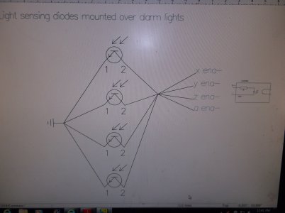
I started thinking about that after i typed it. I would need an output of some kind on an alarm to trigger the others to stop. it may sound silly but i wonder if i could do it with sensors mounted over the red led on each driver since there is no alarm output pin. I know there needs to be something to do it. one axis stopping gets exciting. I ordered fans for all the drivers yesterday but i'd like to address the problem further. If i had this to do over i'd use all dq2722m drivers they output an alarm signal but of course the docs are poor
http://www.wantmotor.com/ProductsView.asp?id=256&pid=75&sid=82
steve
 
That should work for your setup, ensure reliable coupling for sensor to alarm LED. It seems that most of the stepper/servo drive units do have in-line resistors to the opto's tailored for 5v activation. If the opto didn't have an in-line resistor then one needs to be added to each opto for a multi-leg wired-or setup, to ensure that the internal LED junction gets activated.
Some drivers may output a pulse train for alarm, rather than continuous on. My DCS810 servo drives do this, they have 7 alarm pulse sequences (DTC's).
The more adventurous may hack in an opto to the alarm LED, just check the current limiting resistor for that LED allows enough current for the change in combined voltage across both opto & LED.

You might need a manual over-ride if for example the drive faults on power up and you need to do diagnostics.

regards
Andrew
 
these need a full power down to reset. and when the alarm led comes on it stays on no flashing
when you power up the unit it only turns on the green
this circuit is the ground for the controllers enable opto no resister needed
and there is plenty of power the 5v is on its own power supply not the pc
steve
 
ZX45 running at 200 inches per minute
I got the uc100 usb controller in the mail this afternoon and installed the software
there are no more missed steps and this thing is scary at 200ipm
I wont be running over 50 for rapids but the controller problems with windows are solved
I'm very impressed with this product
there is still no new z motor from china i didnt think they would send a replacement the lady keeps telling me it's on the way.
steve

[video=youtube;1jWF1JW1JnE]http://www.youtube.com/watch?v=1jWF1JW1JnE[/video]
 
Looks good, Steve. If you think that rapid is scary, you ought to run something in a 5o taper size 50hp spindle that will do over 2000 IPM. That'll make you pucker. Or a tool changer that will do chip to chip in about 3 seconds. Definitely nerve-wracking. Especially if you have a sadistic (and really, really efficiency conscious) programmer who will rapid up to about 0.050 off the part. You'd never be able to hit the feed-hold quick enough. I always single step through a program at about 50% before I trust a white-knuckler.

I like how this is coming together.
 
thanks tony
yesterday i bought a 30" box pan break / shear and i'm going to start working on the enclosure. I have a few ideas for a design.
steve
 
Back
Top