Rockwell Delta 21-100 Restomod (not restore)

The pulley bearings are installed and in the photo is my version of the bearing lock nut wrench to tighten it all together. This is a simple 1 1/4" cast iron pipe coupler machined down to size. It isn't a hardened socket or anything and I wondered if the cast iron would crack under load, but it worked nicely. Those expensive 2 pairs of duplex bearings were class ABEC 7 and the upper spindle bearing MRC R16FF is ABEC 1. I don't recall seeing any other options on that bearing when I ordered.

What the items are sitting on in the photo is a blank canvas as they say. It is aluminum 9" wide and 10" long by 3/4" thick, marked up and ready go. This will be the foundation of the pulley housing. If my vision works out, it will be quite distinctive.
 

Attachments

  • 20230111_184556.jpg
    20230111_184556.jpg
    565.3 KB · Views: 22
Great progress! I, also have made tools out of cast iron fittings and found some of them to have flaws which are usually visible when machining. They are a good source of relatively cheap stock which usually works out. I still am thinking about a quill return spring.
 
The table is pretty trashed, but has been cleaned a little and 3 divets have been filled. one of them, center table, was into the slot so not a complete circle. That one was larger than 1/2" and the 2 round ones were less than 1/2". I drilled out all 3 to get bare clean walls and bottom. Then, turned some scraps to 3-4 thou large and put a dab of permanent red loctite in each hole and hammered them home. Then, milled, filed them down and put an edge on the slot wall. One of the plugs was a piece of rebar. Above the 2 holes, there is a deep medallion looking imprint maybe an indexable face mill jammed into the table. The blanchard grinding shop wanted too much to surface so I've got a lot of scrapping to do. This will give me a chance to try out my "sawzall" converted to a biax scraper.
 

Attachments

  • 20230112_150606.jpg
    20230112_150606.jpg
    683.6 KB · Views: 15
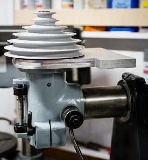
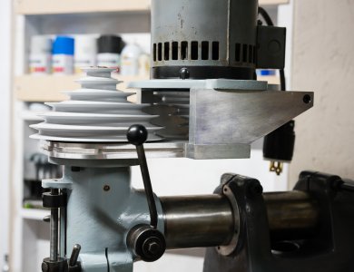
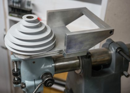
The 3/4" lower aluminum mounting plate has been machined and will be sandwiched in between the pulley/brake assembly and the head flange like the original pulley housing. There are 2 recessed bosses on the top to locate the pulley/brake concentric with the spindle and a shallow recess on the bottom to locate to the head flange. This lower plate will be part of a parallel plate cantilevered structure with the primary purpose of locating and supporting the 50+ lbs motor and pulley. Those 2 rearward tabs will have 3/4" plate vertical sides that the motor base will attach to.

Since the operator only needs to be protected from the front spindle pulley, I've found a cowl that will slide into the 1/4" groove in the sides of this bottom plate.
 

Attachments

  • Rockmill_before.jpg
    Rockmill_before.jpg
    239.9 KB · Views: 26
  • _DSC2705.jpg
    _DSC2705.jpg
    159 KB · Views: 25
The lower plate is in position between the head and pulley. A Gates belt catalog describes pulley manufactures paint the pulleys to protect against rust and provide good belt gripping action, so I did the same. Of the 6 pulleys, I will be utilizing only 3, #3,4,5 from the top. _DSC2709.jpg
 
I love my Rockwell!

I think my fine feed gear is bronze too, buts it's been a while since I was in there.

There's no place for a quill return spring IIRC...

I added pressure fed lube to mine In case you wanted even more stuff to do...
When you take the knee off, you should glue a plug in the hole on the back yo keep chips out of the bevel gears!

Sent from my SM-G715A using Tapatalk
 
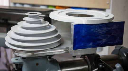
The 2 sides, also 3/4" plate, are screwed to the base with 5/16" cap screws, 3 per side. When I get a counterbore bit I will make the caps flush. There is a diagonal line in the layout paint indicating a possible cut line for the profile of the piece. There is a little room left to take off a bid more height to lower the motor base. Since I have an original 3 phase motor I will complete the build using it, but ultimately get an inverter duty motor with the broad rpm power bands. This will allow me to depend on just 3 of the original 6 pulleys. This also helps with the common standard shaft length of 2.25". The original motor base mounting holes are positioned on the midpoint centerline of the 2 sides. I have material for a cross brace connecting the 2 sides and supporting the motor base if needed.
_DSC2710.jpg
 
When you take the knee off, you should glue a plug in the hole on the back yo keep chips out of the bevel gears!
Chips on the bevel gears? Wouldn't the 2 plates under the saddle and maybe a chip guard covering the vertical knee ways protect against that? If what you suggest is important, I think I can place a foam disc over each of the holes with access from under the knee. I don't plan on removed the knee again at this point.
 
You would think so, but on both my BP, and the Acra that I'm working on now That whole area was covered in chips and built up crud. On the Bridgeport I made a shield to cover the gears and put a grease zerk in the casting with a copper line running to the gear mesh area. The gears themselves were in good shape, so perhaps not really a necessary modifiacation, but as I was there I went ahead and did it. Nice work on the mill, it's really coming along. Mike

Wouldn't the 2 plates under the saddle and maybe a chip guard covering the vertical knee ways protect against that? If what you suggest is important, I think I can place a foam disc over each of the holes with access from under the knee.
 
The frame of the motor mount is all 3/4" aluminum plate held together with a total of 8 5/16" SHCS's.
_DSC2713.jpg
The original motor mount flange is sitting on the 2 side rails. As soon as I can find a suitable 4L belt, I will drill and tap holes in the side rails. The 2 top motor pulleys were sacrificed as top speeds of 3,000 and 4,000 rpms are not priority and I will eventually have to utilize the 2" rotor shaft of an inverter rated motor. Having the motor mounted down as much as possible helps in that regard.

The base is a bit thicker than the original cast aluminum pulley housing, so the spline just barely makes it thru the pulley cone. Without the exoskeleton type aluminum housing, I wanted to keep as much mass for strength as possible.
_DSC2714.jpg
 
Back
Top