Hey guys,
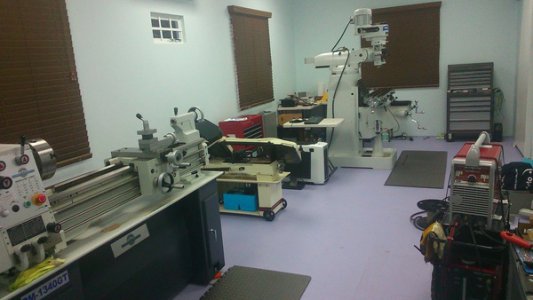
So here's where I'm at in getting my machines up and running. So far all my efforts have been focused on the mill. Besides cleanup and leveling I haven't done anything with the lathe yet. Hopefully I should be able to start working on her later this month.
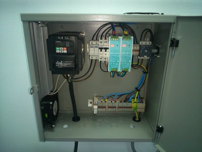
This is the VFD and power distribution system I built (Many thanks to Mark for his wiring diagrams). Apart from powering the VFD it provides 12V and 24V DC power for devices such as work lights, tachometer solenoids and relays. It also supplies 120v to the DRO and powerfeeds. This way all equipment for the machine is powered on or off with one switch.
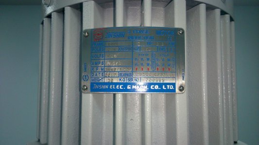
The motor on this machine is a two speed, 3ph, 3HP, constant HP. Below is the motor name plate showing the wiring diagram for the two speeds. I opted to wire it on the low speed side (4(8)P) this way you get double the torque on the low end. For top end speed I would run the VFD between 60-100Hz. On the highest pulley @ 100Hz I should get a top speed of ~4500RPM.
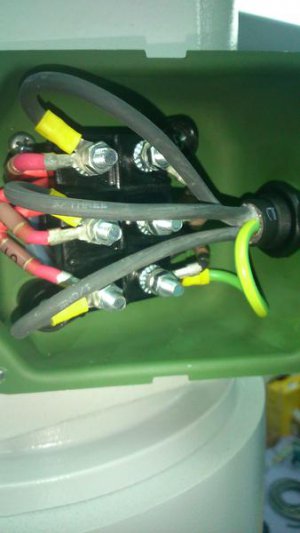
When I opened the motor wiring box I realized that the entry hole for the motor wires had a sharp edge to it. So I took out the box filed the edges of the hole then used some fuel tubing to make a grommet so that the wires have zero change of coming in contact with any sharp edges.
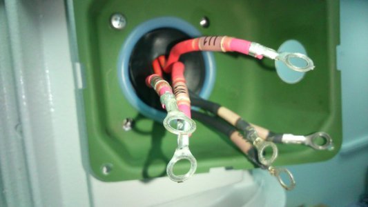
Motor wire up in 4(8)P configuration. For motor to VFD I used 14 AWG shielded VFD cable that has both a braided shield as well as a drain wire.
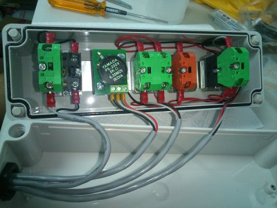
Wiring for my control box. I should have really used a 9 conductor cable for this but I couldn't find any at a reasonable price. I had a good supply of shielded 3 and 2 conductor cable from previous projects so I opted to make use of those.
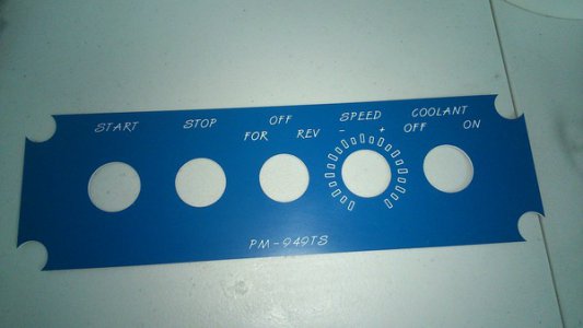
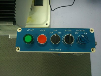
Now I bought legend plates for the direction switch as well as the speed pot. However when I installed them they looked..well I didn't like how they looked lol. So I decided to design and make my own

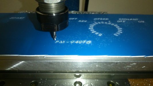
Below is my Taig CNC mill engraving my legend plate. I didn't have the proper V bit on hand so I just used my smallest spot drill and tested at different DOC till the engraving looked right.
Finished plate
I knew from the start I wanted the controls mounted to the knee in front the machine. I don't like (read loathe) drilling holes into machines unless its absolutely necessary such as mounting DRO scales. So I designed and machined a mount for the control box that utilizes the existing M8 bolts on the Y Axis end plate.
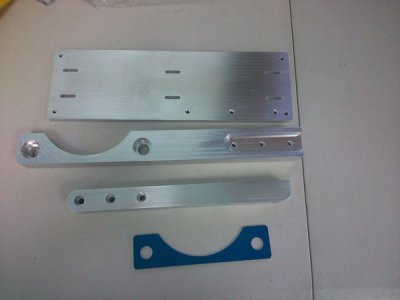
Top to bottom:
1. Switch box mounting plate. The slots cut in it are for 1/2" velcro straps for some cable management.
2. Bracket that mounts to the Y axis end plate
3. Extension that connects the Bracket and the mounting plate together. These two parts could have really been made as one but the Taig mill doesn't have that amount of travel and more importantly I just didn't want to machine one half, index and then machine the second out of one piece of stock.
4. This is an isolator made out of some scrap .062" engraving plastic. The Y axis end plate is aluminum and I wanted to prevent any chance of it galling when the mounting bracket is bolted on top of it.
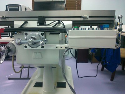
Switch box mount assembled
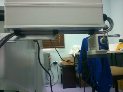
Cable straps
So that's where I'm at. This week I hope to wire up the controls to the VFD and make the mount for the E-Stop switch which will go on the head, where the stock switch was located.
Chevy
