Hi Dan,
I am still a bit confused by your description ("I measured the deflection across the width of the table (i.e. along the Y axis)"), but I suspect that you are doing your measurement correctly. My PM940M is not nearly as precise as your machine (should be). On my machine, the base is made with the y-axis ways machined, all as one piece and I suspect that the column mounting surface is machined at the same time as the way's y-axis reference surface is machined. However, I can see that it would be far harder to machine the end of the column and make it exactly 90 degrees to the z-axis way's reference surface.
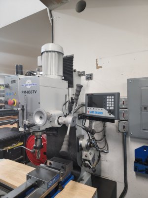
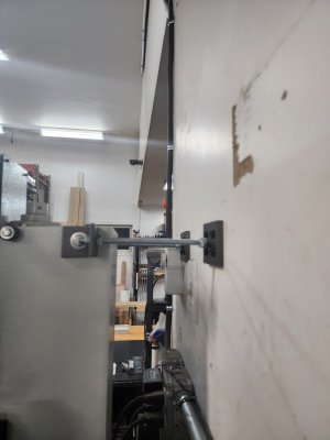
When I look at pictures and manual of your machine at PM it appears to be the same, but I am missing something! In the 833 manual page 31 is an exploded drawing of the machine components (attached). On the top surface of the base piece (#1) the column is mounted by bolting (4 bolts, see #3) to the base at the back of the machine. So there is nothing to shim between at the front (near the operator) of the ways .... if that is what you were describing. The only place to put shims are between the column (#4) and the base at the four bolt holes (where bolts #3 are used). If you put a pair of shims at the two bolts at the farthest back then the column will tilt toward the front of the machine as it goes up. If you put a pair of shims at either side then the column will tilt to one side or the other. Yes, you need a square to check either. If I were to mount a dial indicator via the spindle and touch the table and then run the table along the y-axis (or x-axis) there should be no deflection as the dial indicator is not moving relative to the base y-axis ways. While the y-table should be traveling along the ways the distance to the spindle should remain constant. This would be the case no mater what shims are put under the column-base interface. The conventional way to measure the tram in either axis is by putting the dial indicator in an arm that extends from the spindle z-axis a few inches and then rotate the spindle and swinging this around the 360 degrees taking measurements at the 180 degree locations to compare. Hopefully that is what you are doing. ("I measured the deflection across the width of the table (i.e. along the Y axis)")
If the y-table surface is not perpendicular to the z-axis, z-y angle, shims may still be needed to correct for tram in this direction. This is not to say that the ways along the y-axis are made correctly. It is possible that the table tilts as it travels on the ways, but this would be complex and not fixed with shims under the column. Anyway, we will hope that this is all there is too it. The U-Tube that David Best posted on using the expoxy is useful and is perhaps the way to go. However, before I did this, and possibly made a mess, I would just practice using conventional shims and see how fast you are at it.
In your original post you used the phrase "nod". In my machine the head is extremely heavy due to the gears and oil etc. Hence the head doe actually nod, that is change z-y angle depending upon whether the head is going up or coming down. In fact, if you put an indicator on the head and measure the distance to the table you can find that this distance change can be 0.0015 or more depending upon how tight the z-axis gib is. That is it appears that the head ways make better or worst contact to the column way wear surfaces at the top vs bottom of the head, depending upon the travel direction. The lead screw must be deflecting a bit also. This brings up an interesting question, does one measure the tram on the way up or on the way down. I think the head maybe so heavy that it causes the distance between the ways to be deflecting (squeezing) at the top. You might want to redo your measurement for the two conditions, having just traveled up or having just traveled down. Since, you have the belt driven version (TV) your head should not be so heavy.
Now, let me go a bit farther out on this conjure. Let us suppose for a second that the ways are not made correctly, that they have curvature in them as one measures from the back to the front. That is, the ways might be bowed during manufacture. This might cause the table surface to approach the spindle as the table travels along the ways. My machine actually has a similar problem where the ways surfaces on the left and right are not parallel and also bow... and while I am not talking about the measurement that you are doing, I find that my gib gets tighter as I move the y-axis toward the operator. This results in excessive backlash as the table is moved toward the operator. Hence, I have been slowly sanding (scrapping might be more traditional, but there was a lot of material to remove and I did not want to take the machine apart.) the way surfaces to make the left and right match "better" and reduce the backlash.
Aside: (Skip this part unless you just want to read....more.. especially about dovetails.) The ways that are built into the base have 6 surfaces forming the two dove tails and the two top reference surfaces. Think of the right side and you see that the base has a shape similar to the letter Z. The bottom line in the letter Z is the surface that the y-table slides on. The diagonal line in the letter is the surface that the gib presses against. Nothing touches the top surface, which was ground at the factory to be flat (hopefully) and is the reference surface you can use to measure the distance to the bottom line of the Z, the base way wear surface. In my machines case, I measured from the reference surface to the wear surface, ie from the top of the Z to the bottom of the Z, and found that it varied by several thousands over the y axis travel. This was true on both right and left sides, but was worst on the gib side so this is where I started my sanding to make it flat wrt to the reference surface. It should not vary at all! (Indeed, this is very hard to describe in words, without sketches, but if needed I can make some drawings for you.) I do this measurement via a digital plunging style dial indicator which as a resolution of 1 micron (25micron = 0.001") and a travel distance of 25.4 mm. Of course during this measurement the indicator travel is small compared to 25.4mm so I do not have to worry about the accuracy of the digital indicator over large distances, only the resolution. I use a precision flat bar that reaches clear across the ways and allow it to rest on both left and right reference surface. The indicator is bolted to the end of the bar. This also allows me to move the indicator probe across the wear surface in the X-axis direction (a couple of inches) to see if the wear surface is flat in the x-direction. Of course it is not so the most important location is where the y table ways touch the reference surface. One can also measure the distance between the left and right dove tail if you have a long enough micrometer and you place two cylinders in the dovetails to contact both the bottom and diagonal of the Z surface ( looks sort of like : Zo on the right side) to measure to the outsides of the cylinders. I am planning to build a special fixture to make this measurement.... one of these days. By the way, if you sand the bottom wear surface, the bottom line of the Z, then the Z becomes taller and the cylinders move closer together and the distance between the ways decreases. Of course this also tilts the table along the X axis unless you similar amounts off both the left and right wear surfaces.
Good luck.
Dave L.


