It was a long time coming, but finally I made a choice to purchase PM-932M-PDF Gear head milling machine end of last year.
<o >
>
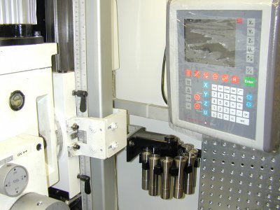
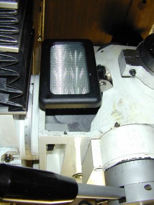
Time was mostly spent on acquiring tools and accessories to be able to do some work. Being a perfectionist installing Easson ES 12 DRO was quite a undertaking. Also found a nice LED powerful lamp.
<o >
>
Not new to PM products as I purchased PM1236 lathe from Matt at <st1 ersonname w:st="on">Quality Machine Tools</st1ersonname> around 2 years ago. Few modifications there as well. I will likely do a little post as well.
<o >
>
Like with any Asian built machine a lot of time was spent taking things apart making sure they were clean and lubricated. If you would ask my opinion about the mill couple month ago I would likely give it a thumbs down. At one point I believed the purchase was a mistake. On the bright side most of the shortcomings were resolved and I am able to perform most of the work to my satisfaction. I would like to remind everyone that I am extremely fussy about my machinery and my tools.
<o >
>
Lets not forget who the market is for this type of machinery. No production shop would even consider them. I on the other hand am grateful, as were there not machinery in this price range I would not own one at all. Especially in here <st1 Western Canada where used worn out machinery goes fot top dollar. </st1
<o >
>
Enough of the philosophy and to the point.
<o >
>
I think PM-932M-PDF is a good piece of gear powerful enough for my type of work. Just the other day I was turning 4” face mill with 6 inserts on a steel block and was very happy with the result. Yesterday I was milling 1” aluminum with extra length end mill with precision that I was not able to accomplish when I first got the machine.
<o >
>
Here is a partial list of shortcomings which I observed, got used to and or coirrected.
<o >
>
Tilting the gear head is a pain and tramming it back to acceptable level is even worse. It would so much nicer to have a bolt in the casting to slowly and precisely move the gear head into alignment. (I am working on that one).
<o >
>
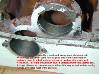
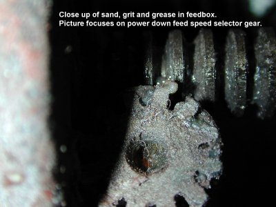
What I know today, I would not attempt to run a mill without taking the feed box completely apart right down to pinion shaft as the feedbox didn’t feel very smooth in operation. I ended up removing the whole feedbox as the girt and sand I found in it made me feel sick. I left the pinion shaft in as the bearings were sealed and appeared good. There were some small springs and tiny parts to keep things interesting.
I made some improvements by fabricating shims of different size. After I cleaned, lubricated and assembled the feedbox I ended up with a very different machine. This was the turning point for me.
<o >
>
This cleaning however; did not correct what I thought to be excessive backlash in manual feed handle. I found pocket milling just about impossible. The included quill DRO was indicating random numbers on different part of the scale (I found out since that few people experience that) it was a joke. Manual scale was another surprise one full turn is 0.110”. One can get used to that but the gearing was likely converted from metric to imperial and it has a 5% error (in my machine anyway). The good thing if you want to call it that is that the 5% error is constant and is negative, so you can mill some more material without spoiling your work.
<o >
>
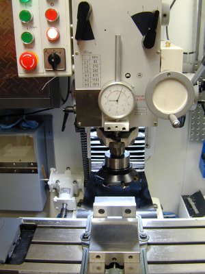
This part was easy. Quill DRO went to the rubbish bin and new 3” travel gauge with 3” diameter large face was installed. Finally I knew where the quill was.
<o >
>
What followed was worse. The backlash in the manual feed turned out to be a backlash between the pinion shaft and the spindle. I believe in the end it turned out to be 0.070”. This can be found by moving feed operation handle outwards and lower the spindle little distance. Now without locking the spindle grab it with your hand and push it up. It weights 18 lbs. My mill went up 0.030 “ by hand but under load it reached 0.070”. This did not have any ill effect if surface milling as once the work was cleared, one could lower the spindle, lock it in place and carry on. Now in pocket milling of harder material the spindle was floating around within the backlash limits causing unpredictable results. Not good in machining.
<o >
>
I know you will say, lock the spindle and move the gear head down, That is a proper way to do it. Well not exactly as new issues arise. Knee end mill anyone? Bring the work up to the spindle, would be nice. No chance we have a gear head mill.
<o >
>
Using the power feed is unthinkable, as moves are uncontrolled and jumpy. Using the crank to lower the gear head is not precise enough for me. Jumpy moves are too large, gearing is just not right.
<o >
>
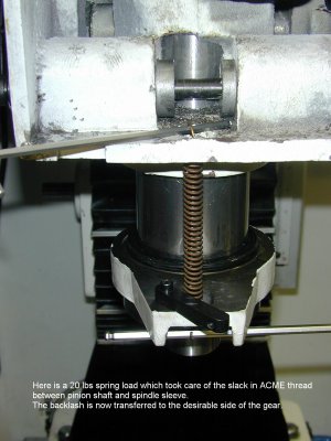
Thinking about the knee end mill got me motivated that all I have to do is overcome the gravity and make the mill work on the other side of the backlash.
<o >
>
Thinking about the poor gearing on gear head crank got me motivated to pursue another idea.
<o >
>
So now I had to come up with two solutions. Improve the gearing for the gear head crank and/or modify spindle to work on the other side of the backlash.
<o >
>
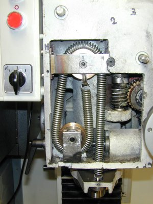
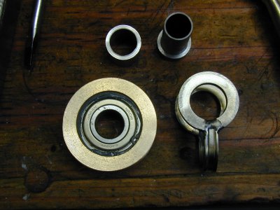
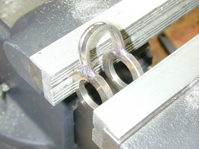
To overcome the gravity I dreamed up a new return spring. Let the pictures speak. The spring is 5/8OD with0.082 wire. The pulleys are small ball bearings with pressed on bronze with concave shape to accept diameter of the spring.
<o >
>
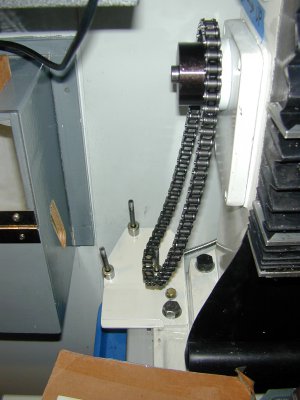
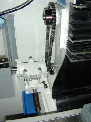
To overcome the clumsy crank location with different gearing I used 1 to 2 chain sprockets and 40 chain. The sprockets ratio can be change in the future should I find the ratio unsatisfactory. The chain is then controlled by US made Andantex R3350 Anglgear with ¾” shaft. Since it takes 71 inch pounds to move the shaft I chose the R3350. The little gear is driven by 5/8” diameter W-1 drill rod (no particular reason just had it around the shop) Coupled by US made Lovejoy universal joint. Shaft is fixed in a bearing on the outer end and rotated by 9.5” hand wheel located beside present Y axis hand wheel. Let the picture speak again. This modification just happened so I can expand on it later.
<o >
>
Should there be someone (eccentric and anal like me) interested in this project, I will be happy to provide more information and I still have couple of “U” joints left.
<o >
>
As far as I am concerned, the spring modification was well worth it as without it I would likely got rid of the machine.
<o
 hew:>
hew:>
Here is the link to my website for closer look at some interesting clean up process. http://www3.telus.net/oceanready/PM-932M-PDF.pdf
Cheers to all.
<o ></o</o</o</o</o</o</o</o</o</o</o</o</o</o</o</o</o</o</o</o</o</o</o


<o
Time was mostly spent on acquiring tools and accessories to be able to do some work. Being a perfectionist installing Easson ES 12 DRO was quite a undertaking. Also found a nice LED powerful lamp.
<o
Not new to PM products as I purchased PM1236 lathe from Matt at <st1
<o
Like with any Asian built machine a lot of time was spent taking things apart making sure they were clean and lubricated. If you would ask my opinion about the mill couple month ago I would likely give it a thumbs down. At one point I believed the purchase was a mistake. On the bright side most of the shortcomings were resolved and I am able to perform most of the work to my satisfaction. I would like to remind everyone that I am extremely fussy about my machinery and my tools.
<o
Lets not forget who the market is for this type of machinery. No production shop would even consider them. I on the other hand am grateful, as were there not machinery in this price range I would not own one at all. Especially in here <st1
<o
Enough of the philosophy and to the point.
<o
I think PM-932M-PDF is a good piece of gear powerful enough for my type of work. Just the other day I was turning 4” face mill with 6 inserts on a steel block and was very happy with the result. Yesterday I was milling 1” aluminum with extra length end mill with precision that I was not able to accomplish when I first got the machine.
<o
Here is a partial list of shortcomings which I observed, got used to and or coirrected.
<o
Tilting the gear head is a pain and tramming it back to acceptable level is even worse. It would so much nicer to have a bolt in the casting to slowly and precisely move the gear head into alignment. (I am working on that one).
<o
What I know today, I would not attempt to run a mill without taking the feed box completely apart right down to pinion shaft as the feedbox didn’t feel very smooth in operation. I ended up removing the whole feedbox as the girt and sand I found in it made me feel sick. I left the pinion shaft in as the bearings were sealed and appeared good. There were some small springs and tiny parts to keep things interesting.
I made some improvements by fabricating shims of different size. After I cleaned, lubricated and assembled the feedbox I ended up with a very different machine. This was the turning point for me.
<o
This cleaning however; did not correct what I thought to be excessive backlash in manual feed handle. I found pocket milling just about impossible. The included quill DRO was indicating random numbers on different part of the scale (I found out since that few people experience that) it was a joke. Manual scale was another surprise one full turn is 0.110”. One can get used to that but the gearing was likely converted from metric to imperial and it has a 5% error (in my machine anyway). The good thing if you want to call it that is that the 5% error is constant and is negative, so you can mill some more material without spoiling your work.
<o
This part was easy. Quill DRO went to the rubbish bin and new 3” travel gauge with 3” diameter large face was installed. Finally I knew where the quill was.
<o
What followed was worse. The backlash in the manual feed turned out to be a backlash between the pinion shaft and the spindle. I believe in the end it turned out to be 0.070”. This can be found by moving feed operation handle outwards and lower the spindle little distance. Now without locking the spindle grab it with your hand and push it up. It weights 18 lbs. My mill went up 0.030 “ by hand but under load it reached 0.070”. This did not have any ill effect if surface milling as once the work was cleared, one could lower the spindle, lock it in place and carry on. Now in pocket milling of harder material the spindle was floating around within the backlash limits causing unpredictable results. Not good in machining.
<o
I know you will say, lock the spindle and move the gear head down, That is a proper way to do it. Well not exactly as new issues arise. Knee end mill anyone? Bring the work up to the spindle, would be nice. No chance we have a gear head mill.
<o
Using the power feed is unthinkable, as moves are uncontrolled and jumpy. Using the crank to lower the gear head is not precise enough for me. Jumpy moves are too large, gearing is just not right.
<o
Thinking about the knee end mill got me motivated that all I have to do is overcome the gravity and make the mill work on the other side of the backlash.
<o
Thinking about the poor gearing on gear head crank got me motivated to pursue another idea.
<o
So now I had to come up with two solutions. Improve the gearing for the gear head crank and/or modify spindle to work on the other side of the backlash.
<o
To overcome the gravity I dreamed up a new return spring. Let the pictures speak. The spring is 5/8OD with0.082 wire. The pulleys are small ball bearings with pressed on bronze with concave shape to accept diameter of the spring.
<o
To overcome the clumsy crank location with different gearing I used 1 to 2 chain sprockets and 40 chain. The sprockets ratio can be change in the future should I find the ratio unsatisfactory. The chain is then controlled by US made Andantex R3350 Anglgear with ¾” shaft. Since it takes 71 inch pounds to move the shaft I chose the R3350. The little gear is driven by 5/8” diameter W-1 drill rod (no particular reason just had it around the shop) Coupled by US made Lovejoy universal joint. Shaft is fixed in a bearing on the outer end and rotated by 9.5” hand wheel located beside present Y axis hand wheel. Let the picture speak again. This modification just happened so I can expand on it later.
<o
Should there be someone (eccentric and anal like me) interested in this project, I will be happy to provide more information and I still have couple of “U” joints left.
<o
As far as I am concerned, the spring modification was well worth it as without it I would likely got rid of the machine.
<o
Here is the link to my website for closer look at some interesting clean up process. http://www3.telus.net/oceanready/PM-932M-PDF.pdf
Cheers to all.


<o


Last edited:

