PM-833TV power switch...

I would put spade connector on the end of the wire, crimp it an be done.
I will wait for the crimp vs solder debate to begin....
I laughed at your mention of the debate, but sure enough, here is begins. What a riot.
 
When you say not just closed with pliers are you talking about soldering as well? As far as a 30 amp wall switch......this is the one I was looking at.

View attachment 364600

That exactly the same switch I use to toggle power to the controls and VFD on my PM1340:

30803613455_80e923e812_k.jpg
 
Just be sure correct number of poles.

SPST okay for 120 volts, DPST for 240 volts

Sent from my SAMSUNG-SM-G930A using Tapatalk
 
Got the switch installed. Wired it backward so the light was on all the time. Got it wired correctly now so the light only comes on when it's in the on position.
switch.jpg
 
Last edited:
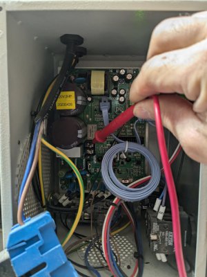
Like others here I have added 220v lockut switch to my 833tv. I put it right on the factory control box and use it to turn the machine main in and off. It should come this way, but whatever. Now I want to streamline all the power stuff on the machine: power feeds, coolant solenoids etc. pulling one legg of the 220v I get is bad. So I was poking around in the box and found the obvious terminal pair the probe is on read 127v when the main power is on. Can I tap into these terminals, run to an accessory power box and distribute 120v from there? It would almost be too convenient!
 

Attachments

  • PXL_20241119_184520429.jpg
    PXL_20241119_184520429.jpg
    239.1 KB · Views: 6
Like others here I have added 220v lockut switch to my 833tv. I put it right on the factory control box and use it to turn the machine main in and off. It should come this way, but whatever. Now I want to streamline all the power stuff on the machine: power feeds, coolant solenoids etc. pulling one legg of the 220v I get is bad. So I was poking around in the box and found the obvious terminal pair the probe is on read 127v when the main power is on. Can I tap into these terminals, run to an accessory power box and distribute 120v from there? It would almost be too convenient!
if the circuit is 220v with 2 hots and a ground (10/2 WG wire) you do not want to use 1 leg for anything it is a safety issue, if the circuit is 2 hots a N and a G (10/3 WG) then you have a shot. the 120v power needs to be H - N not H - G otherwise you are running current on the safety ground leg and are subject to energizing the case of any case grounded item plugged into that circuit or the panel under some failure modes.
 
Im not sure how pulling 120v from terminals inside the machine control could cause a safety issue. If its 120 inside the control i assume its coming from a transformer. As long as everything is still grounded from the 120 tap point. It looks like its 120v H-N power generated inside the control box, but i don't understand the details well enough to see how. And now i wrecked a component on the control circuit board (see other thread:() so i cant test until i get that fixed.
 
Im not sure how pulling 120v from terminals inside the machine control could cause a safety issue. If its 120 inside the control i assume its coming from a transformer. As long as everything is still grounded from the 120 tap point. It looks like its 120v H-N power generated inside the control box, but i don't understand the details well enough to see how. And now i wrecked a component on the control circuit board (see other thread:() so i cant test until i get that fixed.
the above is the fly in the ointment, may not be an issue but it could also have a big impact on your/others health. So find out before using it.
were you measuring from a line to ground? if so that is exactly where you do not want to pull power. power services entrances should only have a connection between N and G at 1 location (unless a transformer is involved), sub panels should have separate N and G pulled to them and they should be isolated. BTW you can get 120v from a 220v circuit just by reading from 1 hot leg to the ground.

as stated above IF the equipment is connected to a 3 wire with ground 220v circuit, then you can find the neutral and use it as a 120v circuit if it is supplied by a 2 wire with ground 220v circuit you should not use it as 120v.
 
Last edited:
were you measuring from a line to ground? if so that is exactly where you do not want to pull power. power services entrances should only have a connection between N and G at 1 location (unless a transformer is involved), sub panels should have separate N and G pulled to them and they should be isolated. BTW you can get 120v from a 220v circuit just by reading from 1 hot leg to the ground.
Measured 127v between those two adjacent terminals. I did not measure either of those terminals to G.... then i mangled a resistor so i cant check until i fix that. I know you can get 120v on 220 single leg to G, which isn't code or smart, But i cannot imagine that one of those terminals in the middle of the circuit board is a G, thus my (yes) assumption that it was coming from an integral transformer. I will test once i fix the disaster i created.
 
Back
Top