
-
Welcome back Guest! Did you know you can mentor other members here at H-M? If not, please check out our Relaunch of Hobby Machinist Mentoring Program!
You are using an out of date browser. It may not display this or other websites correctly.
You should upgrade or use an alternative browser.
You should upgrade or use an alternative browser.
Oh boy, I did it again! PRAZI SD400.
- Thread starter RaisedByWolves
- Start date
- Joined
- May 7, 2023
- Messages
- 2,242
Went out and found the box of rebuilt spring packs to take a pic and found an unexpected surprise.
Here’s a couple pictures of a rebuilt one and a pic of the bunch in their nest.


Each of those probably has somewhere between 50,000 to 200,000 cycles on them and there’s no appreciable wear. The shoulder bolt wears and the 3/8-24 set screw threaded into the end of the modified stripper bolts need replaced every so often, but the bodies of these are remarkably durable.
Can you find the anomaly in this pic?

Here’s a couple pictures of a rebuilt one and a pic of the bunch in their nest.
Each of those probably has somewhere between 50,000 to 200,000 cycles on them and there’s no appreciable wear. The shoulder bolt wears and the 3/8-24 set screw threaded into the end of the modified stripper bolts need replaced every so often, but the bodies of these are remarkably durable.
Can you find the anomaly in this pic?
- Joined
- Sep 10, 2022
- Messages
- 1,131
Went out and found the box of rebuilt spring packs to take a pic and found an unexpected surprise.
Here’s a couple pictures of a rebuilt one and a pic of the bunch in their nest.
View attachment 501426
View attachment 501427
Each of those probably has somewhere between 50,000 to 200,000 cycles on them and there’s no appreciable wear. The shoulder bolt wears and the 3/8-24 set screw threaded into the end of the modified stripper bolts need replaced every so often, but the bodies of these are remarkably durable.
Can you find the anomaly in this pic?
View attachment 501428
Is there a broken bolt on the top spring pack?
Cutting oil is my blood.
- Joined
- Oct 14, 2013
- Messages
- 1,294
For elastic deflection (ie, doesn't bend permanently) and a given geometry, the elastic modulus of the material controls how much it moves for a given force. Aluminum moves about three times more than steel. There's very little difference amongst the steels. Tungsten carbide moves 1/3 as much as steel. Thus, people make long boring bars out of carbide, not Aluminum! The additional stiffness relative to the bar diameter can get you quite a bit farther into a bore!
The next question is how far can you bend it before you either break it or put a permanent bend in it. Aluminum is a LOT of motion before you get a permanent bend, and carbide is a TINY motion. Of course, the forces required to -reach- that bend are radically different Soft steel and tool steel are very different here; much more force required to bend or break the hardened steel.
Sent from my SM-S911U using Tapatalk
The next question is how far can you bend it before you either break it or put a permanent bend in it. Aluminum is a LOT of motion before you get a permanent bend, and carbide is a TINY motion. Of course, the forces required to -reach- that bend are radically different
 Soft steel and tool steel are very different here; much more force required to bend or break the hardened steel.
Sent from my SM-S911U using Tapatalk
- Joined
- Dec 18, 2019
- Messages
- 7,495
But - soft steel and tool steel deflect the same in their elastic region - the region we are typically using on a lathe. So a boring bar made of either, won't have significantly different deflection. The tool steel one with resist marring, scratching, denting, wearing, but it won't really deflect less than the one made of A36, assuming identical dimensions and use.For elastic deflection (ie, doesn't bend permanently) and a given geometry, the elastic modulus of the material controls how much it moves for a given force. Aluminum moves about three times more than steel. There's very little difference amongst the steels. Tungsten carbide moves 1/3 as much as steel. Thus, people make long boring bars out of carbide, not Aluminum! The additional stiffness relative to the bar diameter can get you quite a bit farther into a bore!
The next question is how far can you bend it before you either break it or put a permanent bend in it. Aluminum is a LOT of motion before you get a permanent bend, and carbide is a TINY motion. Of course, the forces required to -reach- that bend are radically different
Sent from my SM-S911U using Tapatalk
- Joined
- May 7, 2023
- Messages
- 2,242
From my seat of the pants experience I can agree with this.For elastic deflection (ie, doesn't bend permanently) and a given geometry, the elastic modulus of the material controls how much it moves for a given force. Aluminum moves about three times more than steel. There's very little difference amongst the steels. Tungsten carbide moves 1/3 as much as steel. Thus, people make long boring bars out of carbide, not Aluminum! The additional stiffness relative to the bar diameter can get you quite a bit farther into a bore!
The next question is how far can you bend it before you either break it or put a permanent bend in it. Aluminum is a LOT of motion before you get a permanent bend, and carbide is a TINY motion. Of course, the forces required to -reach- that bend are radically differentSoft steel and tool steel are very different here; much more force required to bend or break the hardened steel.
Sent from my SM-S911U using Tapatalk
But - soft steel and tool steel deflect the same in their elastic region - the region we are typically using on a lathe. So a boring bar made of either, won't have significantly different deflection. The tool steel one with resist marring, scratching, denting, wearing, but it won't really deflect less than the one made of A36, assuming identical dimensions and use.
This may be true in theory (See my earlier thoughts on academic vs real life) My seat of the pants knowledge differs.
I may or may not be using the correct terminology, but in a hardened state steel is certainly more rigid or stiffer. By how much I have no practical way to measure, just my personal experience in dealing with stamping dies for a couple decades.
This is the kind of thing where I would drive the engineers crazy at work. They point to the book and say it is gospel, I simply make a part that according to the book should work in a similar fashion and eventually fail and it turns the book on its head and fails immediately.
They ask me how I know such things and I tell them its simple, I never read the book.
@twhite
You hit the nail on the head. That looked to be a brand new 3/8-24 set screw that failed under that light spring pressure sitting in that box! There is the off chance that this unit was used and the bolt compromised earlier, but the exposed thread looks pretty pristine, and the break is clean and not oil stained as if it would be had there been a crack present.
And it was stuck together just like that, which was also strange.


Last edited:
- Joined
- May 3, 2020
- Messages
- 369
This may be true in theory (See my earlier thoughts on academic vs real life) My seat of the pants knowledge differs.
I may or may not be using the correct terminology, but in a hardened state steel is certainly more rigid or stiffer. By how much I have no practical way to measure, just my personal experience in dealing with stamping dies for a couple decades.
This is the kind of thing where I would drive the engineers crazy at work. They point to the book and say it is gospel, I simply make a part that according to the book should work in a similar fashion and eventually fail and it turns the book on its head and fails immediately.
From my reading of history, most great achievements were done in the workshop and the lipstick of math and theory was added later. For example, jet engines and early radio.
- Joined
- May 7, 2023
- Messages
- 2,242
Another thing in this vein that drives some people crazy is I usually dont use drawings for the things I make. Some long hand math and crude sketches yes, but drawing up a proper print for a one off part seems like a waste of time that could be better used to correct mistakes I made from not having a print.From my reading of history, most great achievements were done in the workshop and the lipstick of math and theory was added later. For example, jet engines and early radio.
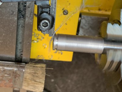
Got the shaft nearly done. I would have finished it and got it ready for hardening but I don't have the proper size set screws for the hole size that was already in the gear.
Made my grooving tool out of an old several times over repurposed tool blank.
I set it up on the grinder with a sine vise at 3* for the side clearance and used a .004 shim for just a smidge back clearance
Came out pretty good.
Looks like the angle is wrong way round on this side, but that is just due to the previous angle that was there when I started.
I have a digital indicator on a magnetic base that I use for setting x travel on the lathe at work as we don't have a digital, for anything under 1" this is perfect, but I needed 1.0735 for this part.

Turned out I had juuust enough extra on the travel of this indicator to get this done.
Literally just enough.

I put the mag base on the tail stock and brought the tool to the required spot.


And then proceeded to make the groove in the shaft.


After that was done I parted the shaft off in the bandsaw and brought the ends to length.

As cut it was a slight interference fit.

But it needed to be so it fits after polishing.
Perfect! Its about .0015 larger than the shaft its replacing for a better fit.

It will need to be polished after hardening again, but I wont lose much if any as that will be mostly to remove the carbonlayer left during the hardening and tempering process.
Im out of space for pics.
.
Last edited:
- Joined
- May 7, 2023
- Messages
- 2,242
- Joined
- May 7, 2023
- Messages
- 2,242
Ok I figured out my problem. I post pics from my phone and type the words on my desktop, as its easier for me to type that way, and its a very fast to add the pics, but things got away from me for a bit.
You should try it some time, great way to mess up your day.
And the gears fit perfectly with a firm sliding fit.
Not today gravity.

I decided to use two opposing set screws vs the tapered pin for strength, And I found the closest size thread to the size holes already present was 4mm-.7 so, so I brought the holes to size for that and tapped both holes.
I figure Ill take this opportunity to show off the cutest lil tap handle I have ever seen in use bu me for the first time. Some kind of watchmakers tool and really the perfect size for small taps under 8-32 or so.
D-Awww. Its only about 2.5-3" long.
Oh, I made the little vise too. Needed something small to use on the 8" drill press and the only thing I could find in a small size that had the features I wanted was a Herman Schmitt that was almost $400. Screw that, I made one better for my needs for free. Aint it cute? 1-7/8" wide with a 2" opening and build in parallels and V notches in both vertical and horizontal orientations. Square all round to .0002 and will be happy in any orientation.

Makers mark.
E.N.W.co #64440

With that done off I went to visit the Amazonians to see what they had to offer for this size set screw.
I was disappointed that I couldn't find the correct screw in the point type on A-Zon contained in one of those 800pcs assortments. so I had to buy a box of 100 from Mrmaster-Carr. So if you need some 4mm-.7 dog point set screws hit me up.
Another pic of the vise in action....just because.

Now let me see if I can hit the save button correctly this time.
.
You should try it some time, great way to mess up your day.
And the gears fit perfectly with a firm sliding fit.
Not today gravity.
I decided to use two opposing set screws vs the tapered pin for strength, And I found the closest size thread to the size holes already present was 4mm-.7 so, so I brought the holes to size for that and tapped both holes.
I figure Ill take this opportunity to show off the cutest lil tap handle I have ever seen in use bu me for the first time. Some kind of watchmakers tool and really the perfect size for small taps under 8-32 or so.
D-Awww. Its only about 2.5-3" long.
Oh, I made the little vise too. Needed something small to use on the 8" drill press and the only thing I could find in a small size that had the features I wanted was a Herman Schmitt that was almost $400. Screw that, I made one better for my needs for free. Aint it cute? 1-7/8" wide with a 2" opening and build in parallels and V notches in both vertical and horizontal orientations. Square all round to .0002 and will be happy in any orientation.
Makers mark.
E.N.W.co #64440
With that done off I went to visit the Amazonians to see what they had to offer for this size set screw.
I was disappointed that I couldn't find the correct screw in the point type on A-Zon contained in one of those 800pcs assortments. so I had to buy a box of 100 from Mrmaster-Carr. So if you need some 4mm-.7 dog point set screws hit me up.
Another pic of the vise in action....just because.
Now let me see if I can hit the save button correctly this time.
.
Last edited:
Similar threads
- Replies
- 12
- Views
- 598
- Replies
- 7
- Views
- 800
- Replies
- 2
- Views
- 104
- Replies
- 17
- Views
- 853