No Fog Coolant Mister

I look at this project and I like it. However I have maybe a silly question. When you mix the water and oil is there any concern that the water will completely separate from the oil and cause rust and corrosion on my mill table and/or vice? I dont typically wipe down things immediately after a quitting for the day. But maybe I need to start. I have a heated garage so I don't have worries or rust otherwise. Just a question I have. Thanks!

I use Kool Mist in my No Fog Mister mixed per the instructions on the container. My shop is not heated and I have not yet had a problem with rust. However, it does get under the vice and discolors the table.

For info I'm converting a PM-932 to CNC and will use the no Fog Mister on it too. No flood coolant for me.

Tom S
 
I used some Kool Mist and some Syn-Kool in my prototype and both worked quite well. A few ounces will last for quite a long time if the unit is set properly. No problems with odor or mist. Air does most of the cooling, with the aid of just a bit of moisture from the coolant itself.

I still have to build my final design and do a build article on it, but time in the shop has been really tough to come by as of late.
Hi Wermie, How is the final design coming? I have my Lagun about ready to go except for the cooling system. Ski
 
It is done. I managed to work on it a little here and there, and have used it a couple of times now. I just need to get some photos taken and posted. Will try to get that done this afternoon.
 
I discovered that the .040" ID for the nozzle was an error, it works much better at .090". Alternatively, the nozzle could be eliminated altogether, as the extension tube also has an ID of .090". I have updated all of the drawings, all are noted as being placed in the public domain, and they are now available in post #1 of this thread.

I also have photos!

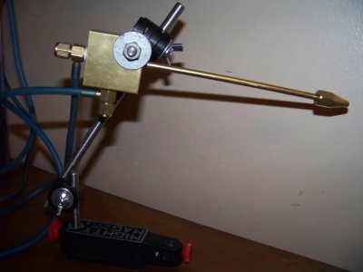
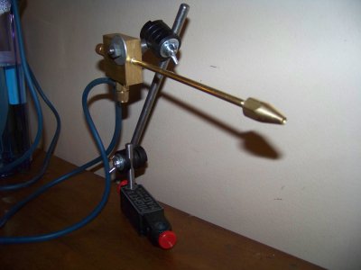
The first one shows the mixing block assembly mounted on the Clausing mill. The Mini Mag mount works quite well, and the arms and clamp assemblies are of my own making. The clamp assemblies are made from black acetal and the rods are simply 5/16" mild steel rods. The clamp assemblies required the use of fine thread bolts to get enough clamping pressure to keep everything in place. The valve on the left side of the mixing block controls the air flow, and the one on the bottom controls the volume of coolant. It can be adjusted to use only air, only coolant, or a mixture of the two. The ideal setting using a nice flow of air, with just enough coolant to barely get things damp. It works well anywhere from 10 to 25 PSI. High pressures and flow rates could potentially cause it to atomize the coolant, creating the dreaded fog in the air, not what we want!
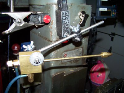
100_1127.JPG


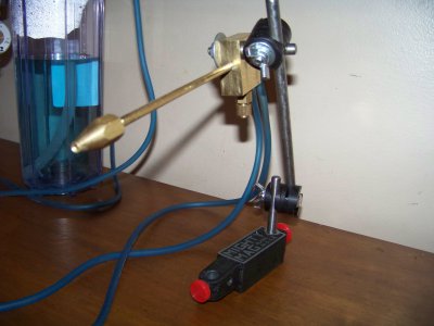
The next photos are shots taken from various angles, showing the whole system off of the mill. The coolant in the reservoir has been in there since the tool was completed, which was back in September or October. It is a heavy mixture of Rustlick Synkool (thus the blue color) and it has not had any problem with bacterial growth. I brought the entire system in from the garage and placed it in the basement before the freezing weather came this past fall. No problems so far. The nozzle could be omitted since it's ID is the same as that of the extension tube, but it helps to counterbalance the mixing block. These photos also show the small ball valve between the regulator and the reservoir. It is used to stop and start the flow of air and coolant without disturbing the pressure regulator or the needle valve settings. You can ignore the female quick coupler for compressed air, I needed a pipe plug for that port of the brass cross and didn't have one, also did not have a tee instead of the cross, so the coupler is a stand-in.
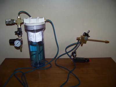
100_1183.JPG100_1184.JPG
100_1185.JPG100_1186.JPG

So far I am quite satisfied with it, and plan to make another one for WD40. As I mentioned elsewhere, I plan to mount both of them on an old IV stand on wheels, allowing me to easily switch to the proper coolant for ferrous materials or for aluminum, and will allow me to easily move them back and forth between the lathe and the mill. When I make the new one for the WD40, I will take photos as I go and post them here as well. Construction is very straight forward, and is quite easy. The only thing I will recommend is to take your time when drilling the .040" coolant passage in the mixing block. Use a high RPM, and advance the drill slowly, bringing it back out often to clear the chips. If you drill the .090" air passage first, be extremely careful to not break the .040" drill bit when it breaks through into the .090" passage.

If anyone is interested in drawings for the rod clamps, I have included it here also: View attachment Rod Clamp.pdf

Enjoy!!

100_1127.JPG 100_1183.JPG 100_1184.JPG 100_1185.JPG 100_1186.JPG
 
Thank you Terry for the updated information. Looks like you saved me from having to buy the Noga unit.


Regards
Darrell
 
Thanks Terry,

I have built this no fog mister as per your plans but cannot seem to get it to work as expected, I either get no mist at all or it starts to drip when the needle valve is opened a touch more then it sprays coolant everywhere if opened more.

The only variations to your design is due to Australia using the metric system so I cannot get everything exact, the spray tube is 0.1mm ID instead of 0.09mm ID, the small hole for the coolant is 1mm instead of 1.016mm and the tube inside the reservoir is 8mm instead of 6.25mm, otherwise everything is identical, I have the air pressure set to around 20psi and have varied that up and down to no avail.

I have no idea where to look for solutions, I can post pictures, but it would look pretty much identical to your images.

Any suggestions would be appreciated.

Eric
 
Hi, Eric. Thanks for posting about your problem. I wonder if your expectations were different from what the design is meant to deliver? I see no problems with the dimensions that you used, they are very, very close to the originals and should work just fine.

In operation, turn on the air first, just that it is blowing a little bit, but it should not be hissing loudly. Next turn on the coolant, only slightly, just enough that your finger barely starts to get wet if you hold your finger in front of the nozzle. The amount of coolant coming out will be so little that it is almost invisible, but it is enough to lubricate and cool your cutters.

It is not meant to be a 'mist' system at all, in fact the desire is to not have any mist so that it does not hang in the air in your shop. Instead, it produces very small droplets, but does not atomize the coolant. Some coolants will appear to come through in larger droplets, which is okay too. The old siphon mist systems require quite a bit of air flow in most cases and tend to atomize the coolant, allowing it to create a fog or mist in the air. This design uses air pressure to push the coolant to the mixing block, then uses moving air to carry the fluid out to the work.

Is it possible to atomize the fluid with this system? Yes, if you use high air pressures and high air flow rates. So, keep the pressure at or below 20 PSI, keep the flow rate low also. With the nozzle placed within a couple of inches (40 mm) of the cutter, there should be just enough air moving to blow small chips away from the cutter. Air at that rate will be moving fast enough to carry the small droplets of coolant to the work.

I will see about doing a video of mine this weekend, if there is time. I have a class to teach this evening, and have to go out of town for work already on Sunday, but I might get time on Saturday. If not, I will put it at the top of my list for the following weekend.
 
Thanks for the reply Terry, I used the wrong term when I said 'mist' I simply meant minute coolant drops, which is what I was looking for, I tried many settings with a tissue in front of the nozzle but saw no moisture except when it started to drip, I'll keep experimenting and look forward to your video.

Eric
 
Hi Terry,
Thanks for sharing all of this. I have a Sherline 2000 CNC for which I've just built an enclosure (see thread under Sherline) with the hope of confining swarf and vagrant coolant. I'll be cutting complex surfaces out to the machine's horizontal limits but not a lot of Z. Aluminum. Your device looks like just the thing in terms of getting some coolant effect without a lot of mess. It also looks like the straight tube is necessary although since it's easy to make, maybe subject to some experimenting in terms of length and maybe curvature . Size of the Sherline encourages getting the size of this thing down to minimum. I also need to mount it on the spindle head and can add a bracket to the motor mount to support the device.

Before I get into this, have you had any other thoughts or experiences with yours which might influence what I do?

John
 
Back
Top