Working up a project for my Dad, His hobby has been wood boats, His/our first boat was a Keeler craft 16' lapstrake bought in 1965, it was a 1961 boat so I was 4 years old when we bought it, We still have it, in fact my brother and I are just finishing up it's third restoration. Actually his first boat was a folding canoe that he built when he was about 12, it was about 6 feet long and folded in half, had wheels he hooked on it and he towed it behind his bike down to the local slough to paddle around. He has since built /restored several wooden boats including strip built kayaks that he loves to go paddling in, unfortunately at 80 his hands aren't what they used to be, due to a chipper accident his right hand has only the thumb and forefinger left and the arthritis has left it pretty non functional and the left has arthritis as well plus there is the non repairable rotator cuff, you get the idea, so paddling has become very difficult.
Our solution is to build an outboard motor for the kayak so he can still enjoy getting out on the water, this is a 3 generation project with my son involved with the motor and controls as well.
What I have designed is a three piece aluminum housing that threads together, I'll include drawings with the post, I found a "high efficiency" prop form a company that makes electric Kayak motors, imagine that, so we could just buy the whole thing for a little over 2 grand but where's the fun in that right?.
I have the design pretty close but where I'm having issues is figuring out the work flow, 2 of the parts need to be machined from both ends and stay concentric and the parts have to thread together and stay in alignment.
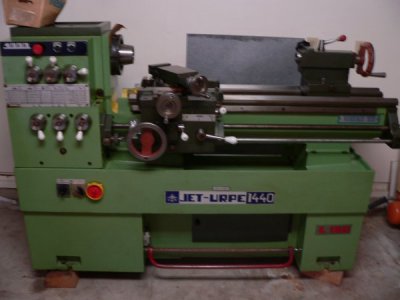
I have a pretty good lathe, I think, but I only have a 3 jaw chuck so if I flip the part it wont run true and what I have to turn from the other end is the other bearing pocket and the attachment threads so even a few thou could be a problem for alignment. I do have a 5C collet chuck but that only gets me to 1" and the material I'll be working with is 3" and all the turning is ID turning so I don't think turning between centers would work plus I don't have mandrels or dogs. I do have a small cnc mill, Grizzly round column drill/mill but I don't think the accuracy is very good, it's pretty worn and has some vibration issues. I also have a decent manual knee mill although my tooling is limited for all the machines. Oh I do have a 4 jaw chuck on my first lathe but it is a well used 1905 Seneca Falls star lathe, not going to provide the accuracy needed.
My background is not machining, I started out in the electronics industry, followed by running heavy construction equipment for a bunch of years, The Seneca falls lathe came first as a gift... "Get it out of here or it's going to the dump" I worked on it and got it running and fell in love with making chips so I bought the cnc mill to play with and quickly found it's limits. The bigger lathe and mill came along when I wasn't even thinking of new equipment but a friend of my brother's was selling his family's equipment, they hadn't used it in about 20 years and he was trying to clear out some space so I bought them.
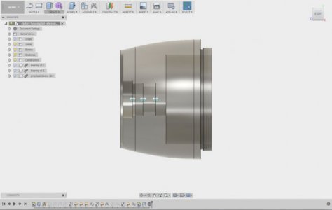
Here is a screen capture of the assembly in Fusion 360 for reference.
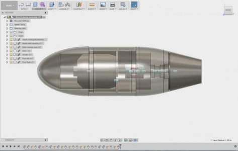
There are 4 components in the body in this view, the nose cone which threads into the center section which the motor mounts in, then the tail housing has the prop shaft, bearings and seal and threads into the center section using a small love joy type coupler to hook to the motor. This view also has the prop hub modeled on the back.
Here's my thought process for work flow hopefully you guys can point out the holes in my thinking and maybe fill some of them as well.
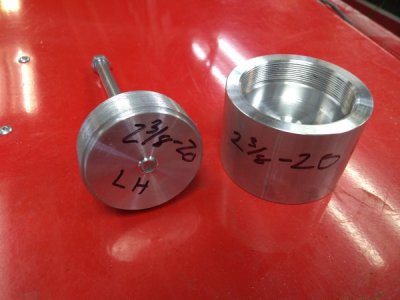
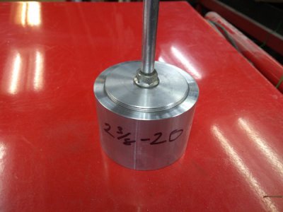
Start by making the thread gauges for the 2.375 X 20 LH threads, then start the center section and cut the back side where it mounts to the tail section, get the internals finished on that end. Follow that with starting the front side of the tail section and do everything on that side then screw the center section on to it and finish the front side of the center section while mounted to the tail section that's still in the chuck. At this point I could rough down the outside of the center section.
Then make a blank female thread so I could thread the tail section into it and finish the back side of the tail section and rough down the OD.
Next I would rough out the nose cone inside and threads, probably do the strait bore as well.
Then put the nose cone in the cnc mill and let it contour the inside of the cone.
Now move the female thread blank into the cnc mill, mount the tail section and let the cnc cut the outside profile on the tail section followed by the outside profile of the nose cone. at this point all the parts should be roughed out and I would need to do a male thread blank in the lathe so I could mount the center housing and tail section to finish the outside, hopefully just a bit of filing and sanding/polishing, followed by mounting the center section and nosecone for the finishing process.
I chose left hand threads because the rotation of the mill cutter will be tightening the part as it cuts the outside profiles so I'll have to flip my lathe tooling or work on the back side with the lathe running backwards to get the same tightening effect, I figure that is easier than reversing the direction of the mill and getting LH cutters for it.
I have included drawings of the parts in pdf and dwg format and a screen capture of the tail section because the drawing didn't pick up the hidden lines on the inside like it did on the other 2 and I haven't figured out why yet.
This is the most ambitious machining project I have come up with yet, am I nuts for trying this? any and all suggestions are welcome including the "What the H*** are you thinking type" LOL.
I'm sure I left out some needed information so please don't hesitate to call me on what's missing.
Thanks
Brian
Our solution is to build an outboard motor for the kayak so he can still enjoy getting out on the water, this is a 3 generation project with my son involved with the motor and controls as well.
What I have designed is a three piece aluminum housing that threads together, I'll include drawings with the post, I found a "high efficiency" prop form a company that makes electric Kayak motors, imagine that, so we could just buy the whole thing for a little over 2 grand but where's the fun in that right?.
I have the design pretty close but where I'm having issues is figuring out the work flow, 2 of the parts need to be machined from both ends and stay concentric and the parts have to thread together and stay in alignment.
I have a pretty good lathe, I think, but I only have a 3 jaw chuck so if I flip the part it wont run true and what I have to turn from the other end is the other bearing pocket and the attachment threads so even a few thou could be a problem for alignment. I do have a 5C collet chuck but that only gets me to 1" and the material I'll be working with is 3" and all the turning is ID turning so I don't think turning between centers would work plus I don't have mandrels or dogs. I do have a small cnc mill, Grizzly round column drill/mill but I don't think the accuracy is very good, it's pretty worn and has some vibration issues. I also have a decent manual knee mill although my tooling is limited for all the machines. Oh I do have a 4 jaw chuck on my first lathe but it is a well used 1905 Seneca Falls star lathe, not going to provide the accuracy needed.
My background is not machining, I started out in the electronics industry, followed by running heavy construction equipment for a bunch of years, The Seneca falls lathe came first as a gift... "Get it out of here or it's going to the dump" I worked on it and got it running and fell in love with making chips so I bought the cnc mill to play with and quickly found it's limits. The bigger lathe and mill came along when I wasn't even thinking of new equipment but a friend of my brother's was selling his family's equipment, they hadn't used it in about 20 years and he was trying to clear out some space so I bought them.
Here is a screen capture of the assembly in Fusion 360 for reference.

There are 4 components in the body in this view, the nose cone which threads into the center section which the motor mounts in, then the tail housing has the prop shaft, bearings and seal and threads into the center section using a small love joy type coupler to hook to the motor. This view also has the prop hub modeled on the back.
Here's my thought process for work flow hopefully you guys can point out the holes in my thinking and maybe fill some of them as well.
Start by making the thread gauges for the 2.375 X 20 LH threads, then start the center section and cut the back side where it mounts to the tail section, get the internals finished on that end. Follow that with starting the front side of the tail section and do everything on that side then screw the center section on to it and finish the front side of the center section while mounted to the tail section that's still in the chuck. At this point I could rough down the outside of the center section.
Then make a blank female thread so I could thread the tail section into it and finish the back side of the tail section and rough down the OD.
Next I would rough out the nose cone inside and threads, probably do the strait bore as well.
Then put the nose cone in the cnc mill and let it contour the inside of the cone.
Now move the female thread blank into the cnc mill, mount the tail section and let the cnc cut the outside profile on the tail section followed by the outside profile of the nose cone. at this point all the parts should be roughed out and I would need to do a male thread blank in the lathe so I could mount the center housing and tail section to finish the outside, hopefully just a bit of filing and sanding/polishing, followed by mounting the center section and nosecone for the finishing process.
I chose left hand threads because the rotation of the mill cutter will be tightening the part as it cuts the outside profiles so I'll have to flip my lathe tooling or work on the back side with the lathe running backwards to get the same tightening effect, I figure that is easier than reversing the direction of the mill and getting LH cutters for it.
I have included drawings of the parts in pdf and dwg format and a screen capture of the tail section because the drawing didn't pick up the hidden lines on the inside like it did on the other 2 and I haven't figured out why yet.
This is the most ambitious machining project I have come up with yet, am I nuts for trying this? any and all suggestions are welcome including the "What the H*** are you thinking type" LOL.
I'm sure I left out some needed information so please don't hesitate to call me on what's missing.
Thanks
Brian

Attachments
-
Kayak motor housing Drawing v3.dwg98.3 KB · Views: 17
-
Kayak motor housing Drawing v3.pdf68.1 KB · Views: 11
-
Motor housing nose Drawing v1.dwg98.3 KB · Views: 4
-
Motor housing nose Drawing v1.pdf87.7 KB · Views: 9
-
Motor housing tail extension Drawing v1.dwg90.1 KB · Views: 3
-
Motor housing tail extension Drawing v1.pdf69.5 KB · Views: 8

