I made some new lock nuts and machined some spacers for the AC bearings. I suspect some of the .008" backlash was coming from the bearings I was using and I don't think they were preloaded properly. I made 2 piece nuts with screws that can be tightened to lock the nut down on the threads. These are much better than the lock nuts that came with the ballscrews and in my opinion, they are better than the nylon lock nuts. Since it was an M12x1 thread, I couldn't commercial nuts for it anywhere anyway. They use 3 4x40 screws to lock and I cut the holes so there was just a little bit of space between the nuts when the holes are aligned. I have always had trouble with the regular lock nuts occasionally loosening up and it has ruined parts before. I am confident that these won't move once locked.
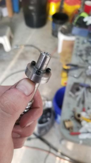
Here it is installed on the X axis with the new coupler on the motor.
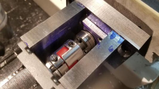
I machined some spacers so I could preload the AC bearings as well. That was pretty straight forward but I don't have any pictures of it. Essentially I machined a bar to the right inside and outside diameter, then parted off 3 pieces, then super glued each to a piece of steel in the spindle, and faced it until it was about .05" thick. Using the lock nuts, I can adjust the preload on the bearings without needing shims.
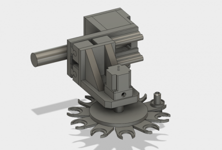
I have the tool changer mostly designed now. It will be a little while before I am ready to start making parts for it, but I will start ordering stock and parts soon. The plan is to use a Nema 23 motor, a deep groove ball bearing, some round linear rails, and a pneumatic cylinder to run it. I think I will use an arduino to control the changer if I can figure out how to interface it with LinuxCNC. The plan is to have several sensors checking each step of the tool change to ensure reliability.
The tool change will go like this:
1. Z axis return to home position (Home switch confirm head in position)
2. Spindle motor off (Relay on spindle power to ensure spindle motor off)
3. Tool changer move into position below spindle (sensor to confirm changer in position)
4. Z axis lower tool to tool changer (sensor confirm head lowers to tool tray)
5. Pneumatic cylinder release tool (sensor to confirm cylinder actuates)
6. Z axis return to home position (home switch confirm head in position)
7. Tool changer rotate to the next tool (sensor to confirm position of carousel and proper tool selected)
8. Z axis lower spindle to tool (sensor to confirm head lowers to tool tray)
9. Release pneumatic cylinder (sensor to confirm cylinder releases)
10. Retract tool changer (sensor to confirm tool changer fully retracted)
11. Z axis return to home position (home switch confirm head in position)
12. Confirm new tool in spindle (not sure how I will do this yet)
Here is the tool changer with all of the covers removed.
Other side.
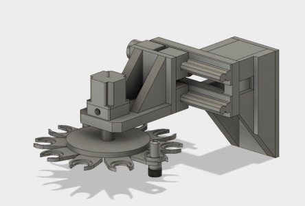
On the mill.
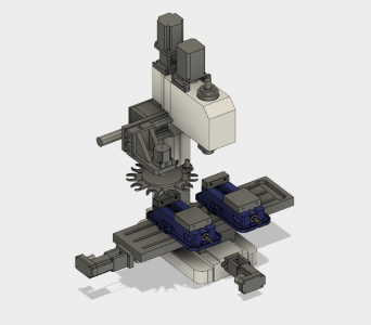
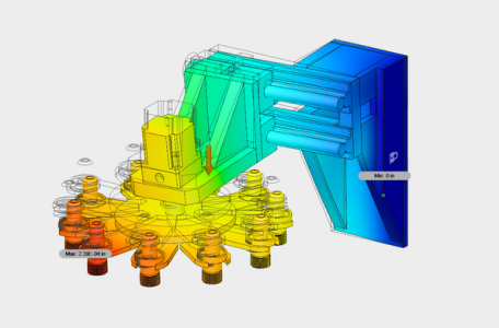
I used Fusion360s FEA to make sure the changer wouldn't deflect too much under the weight of all the tools. It gave me a deflection value of .0002" at the worst position so I am confident the structure is strong enough.
With a vise installed, there will only be about 5.5" between the bottom of the tool holders and the top of the vise jaw. I am considering a few alternatives such as adding a Z axis to the tool changer so it lifts up and out of the way when not in use, and the table can move all the way forward (closest to me) when changing tools, so hopefully it will be mostly out of the way. I don't think it will be too much trouble though, since I don't plan to have any tools sticking out more than 2 inches, and I don't often work with parts sticking more than 3.5" out of the vise. Im pondering the idea of some kind of quick release for the tool changer so I can lower the tool carousel out and remove it completely for when I work with taller parts.
If anyone has any ideas or suggestions, I am all ears. I have never tackled a project like this and could use all the help I can get.


