New bike project.

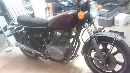
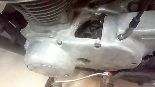
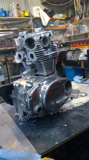
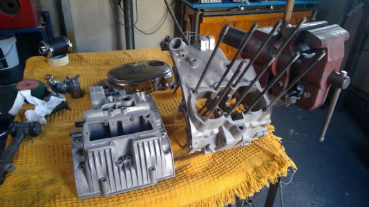
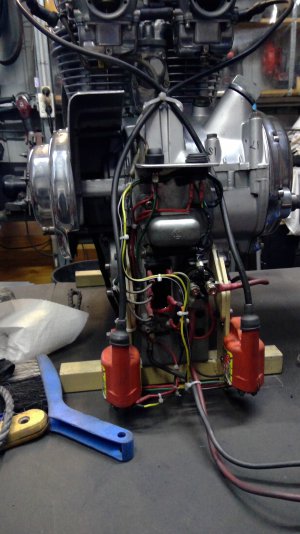
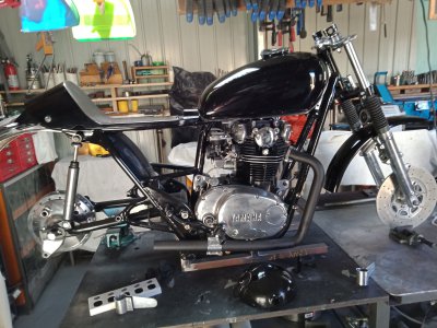
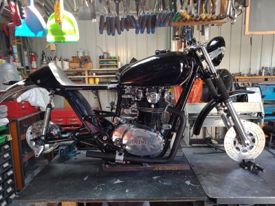
New project, a bike with a motor this time, I’ve been working on this for a while so done quite a bit so far. It’s been 20 years since I sat or worked on a bike, last one was a Triumph Bonny, they just cost too much these days so I settled for a 74 TX650 wreck and boy did it turn out to be a wreck. I have psoriatic arthritis so I’ve largely lost the use of my hands but I manage a few hours work on it every day. I’ll never be able to ride it thanks to the PsA so this will be a long term project: Every nut, bolt spoke, piece of steel was rusted through. Inspection also revealed the chain had come off at same stage, as well as removing the top section of the crankcase as in the picture, it also tore the top section of the gearbox drum shifter bearing housing off. After tearing the engine apart I sent off for a second hand set of crankcase.

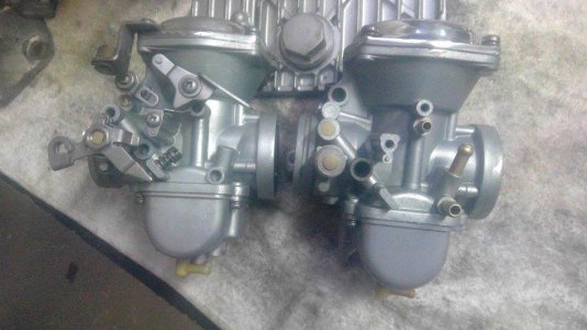
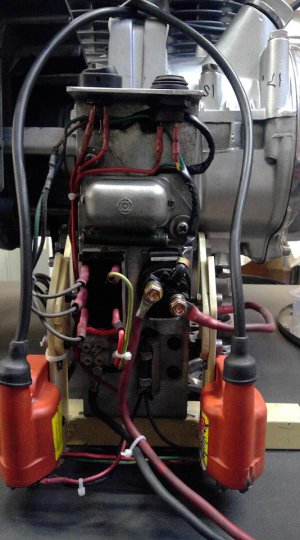
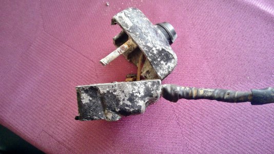
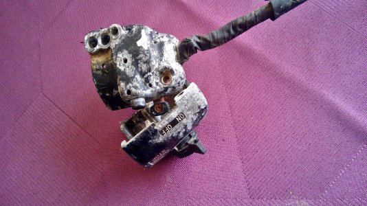
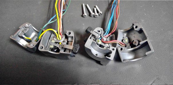
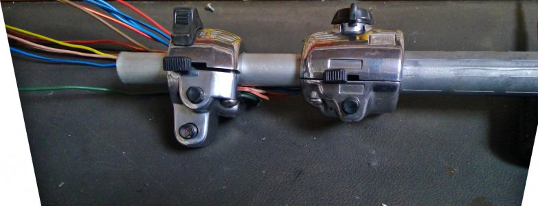
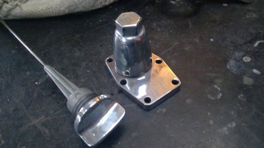
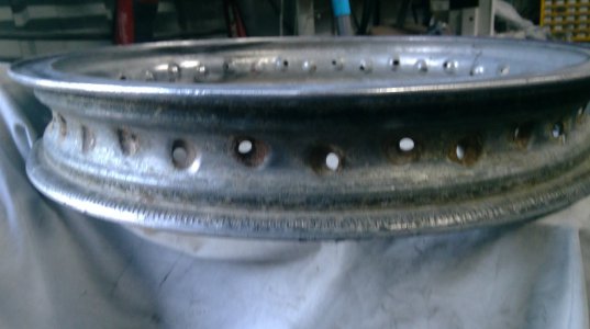
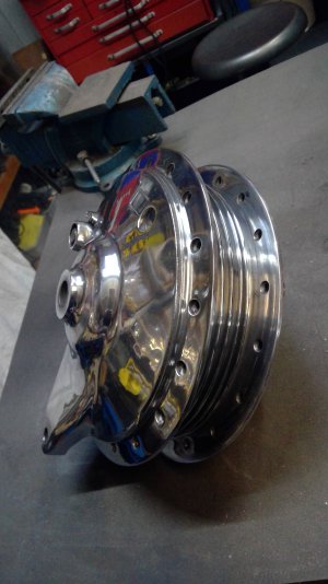
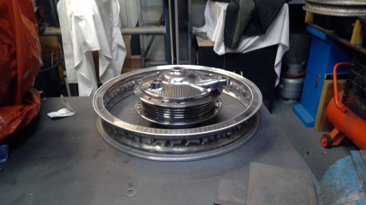
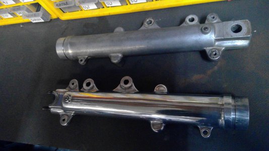
The bike came with an extra set of carbs, mag wheels and a pair of spoked wheels and a box of assorted bits and pieces. While I was waiting for the cases, I cut the rusted spokes off the wheels, stuck the hubs on the lathe, trued up the castings and then polished them using cloth wheels and progressively finer compounds. The rims, which were badly damaged from tyre irons and badly pitted from oxidisation, were repaired, ground and polished. While on a polishing kick I also polished the top triple tree, lower fork sliders, brake backing plate, brake fluid distributor, brake master cylinr and also bead blasted the switches and polished them up. Polishing on the buffer machine really hurts my hands so I have to loop a roop around my neck, tie it to the item to be polished to support it and then polish. It took quite a while to do the polishing as I could only manage an hour or under each day, any more and I’d be laid up recouperating for a few days. A very painful job for me, polishing. Some pics of the journey:
 

Attachments

  • yambarn.jpg
    yambarn.jpg
    88.1 KB · Views: 855,411
  • casehole.jpg
    casehole.jpg
    58.7 KB · Views: 152
  • carbs1.jpg
    carbs1.jpg
    70.8 KB · Views: 107
  • cover.jpg
    cover.jpg
    61.4 KB · Views: 93
  • cover2.jpg
    cover2.jpg
    60.1 KB · Views: 101
  • engine.jpg
    engine.jpg
    77.8 KB · Views: 104
  • electric1.jpg
    electric1.jpg
    148.4 KB · Views: 102
  • switch.jpg
    switch.jpg
    530.7 KB · Views: 103
  • switch1.jpg
    switch1.jpg
    672.8 KB · Views: 99
  • switch 5.jpg
    switch 5.jpg
    409.8 KB · Views: 92
  • switch 4.jpg
    switch 4.jpg
    189 KB · Views: 91
  • cases 1.jpg
    cases 1.jpg
    86.3 KB · Views: 87
  • dipcam.jpg
    dipcam.jpg
    55.6 KB · Views: 84
  • rim.jpg
    rim.jpg
    216.8 KB · Views: 87
  • WIN_20190808_17_09_25_Pro.jpg
    WIN_20190808_17_09_25_Pro.jpg
    574.2 KB · Views: 90
  • WIN_20190808_17_04_49_Pro.jpg
    WIN_20190808_17_04_49_Pro.jpg
    1.9 MB · Views: 91
  • sliders.jpg
    sliders.jpg
    362.8 KB · Views: 91
  • WIN_20190811_17_41_04_Pro.jpg
    WIN_20190811_17_41_04_Pro.jpg
    653.3 KB · Views: 111
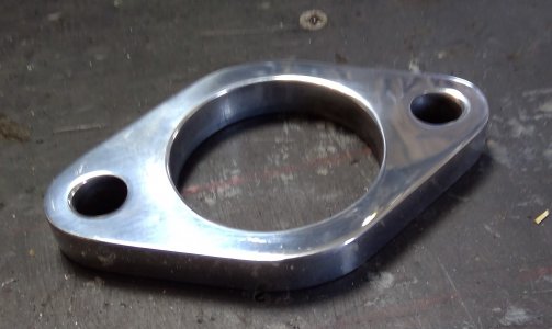
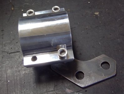
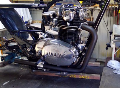
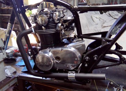
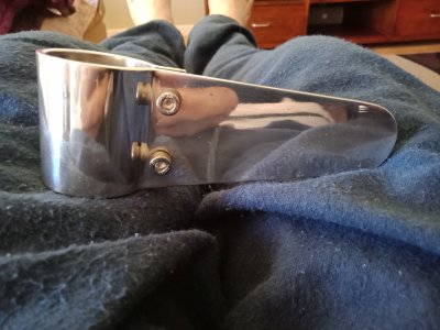
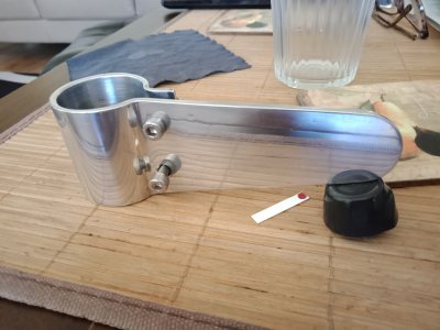
Pipes, brackets and clamps all done. Slapped some paint on and bolted them up. An absolute nightmare grinding, filing and smoothing all the pipe bender marks off, these pipe benders make such a mess of the pipe. Then there was Cutting and then welding the sections together, round tube right? Nope, not very round at all, get one side lined up nice and flat and another section doesn't quite line up. Not far out, but enough to notice. Lots of bashing and grinding and filing.

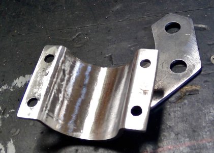
The top bend was such that the downpipe was to match the angle of the frame downtubes, that didn't happen, exhaust shop got that wrong. Not much I could do about that, but probably not that noticeable unless you get on your hands and knees to line the tubes and pipes up. The lower bend was way out, pipe was meant to run parallel to the ground. So, I cut the pipe further along and angled it up so it was parallel, didn't like that, so cut and welded again with a slight upsweep. That then threw the lower bracket angle out, once again, cut and reweld. All good in the end. I got the angles absolutely spot on, so both brackets are identical.

The top clamps were turned on a lathe using a four jaw to get the large central hole lined up. Managed to get them spot on, just using a punch mark and a dead centre. The lower brackets have very tight bends to get the bolts as close to the pipe as possible. Ally was easy, but the 50x3mm steel was a little more difficult, first bending in the bar bender, then bashing them in a vice.

I'd like to know why, when forming circles, or half circles in this case, PI is always incorrect by a couple of mm. Pi says these half brackets needed to both be 65.155mm long, including the right angle bends at each end. Now that is for the two halves to meet. I ended up making them 67.5 long including bends and that left a gap of 1mm once clamped together, which is what I was after.

I've done a lot of these type clamps over the years, Pi is always out, but it does give a ballpark length.
 

Attachments

  • WIN_20201119_14_39_09_Pro.jpg
    WIN_20201119_14_39_09_Pro.jpg
    258.2 KB · Views: 25
  • WIN_20201119_14_39_26_Pro.jpg
    WIN_20201119_14_39_26_Pro.jpg
    488.4 KB · Views: 18
  • WIN_20201119_14_44_59_Scan.jpg
    WIN_20201119_14_44_59_Scan.jpg
    365.5 KB · Views: 23
  • WIN_20201119_15_03_07_Scan.jpg
    WIN_20201119_15_03_07_Scan.jpg
    880.3 KB · Views: 24
  • WIN_20201119_14_47_39_Scan.jpg
    WIN_20201119_14_47_39_Scan.jpg
    877 KB · Views: 27
Last edited:
I had one of these back in 84. Always bought handle bars by the pair. I think I might have liked beer back then. Keep the rubber side down.
 
Due to lack of interest there will be no more progress reports on the build.
I am sure there is interest. I just happen to see this myself. I post for myself and if it helps someone down the line then it is a benefit. No way I can match at the shop level what some of these guys (and gals?) can pull off. Think I am joking just have a look at my belt sander.
 
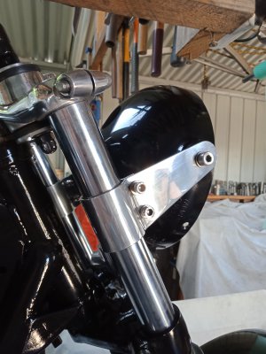
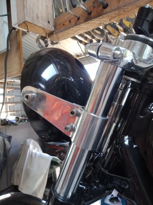
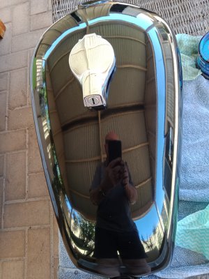
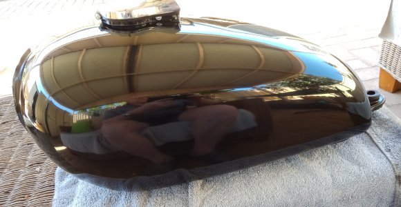
Since a couple are interested, Just a quick update: painted tank, front guard and headlight and made up a couple of headlight brackets. Paintwork yet to be polished, also have a couple of 650 stickers I'm thinking of applying to the tank. Not sure about them, don't want to draw attention away from the engine. If anyone is interested I can post some pictures and write a 'how to' narrative on making the headlight brackets.
 

Attachments

  • IMG20210107161549.jpg
    IMG20210107161549.jpg
    2.5 MB · Views: 26
  • IMG20210107161631.jpg
    IMG20210107161631.jpg
    3.1 MB · Views: 20
  • IMG20201230172856.jpg
    IMG20201230172856.jpg
    2.8 MB · Views: 19
  • IMG20201230174755.jpg
    IMG20201230174755.jpg
    2.6 MB · Views: 20
  • IMG20210102153246.jpg
    IMG20210102153246.jpg
    3.2 MB · Views: 18
  • IMG20210102153313.jpg
    IMG20210102153313.jpg
    1.3 MB · Views: 22
  • IMG20210102162521.jpg
    IMG20210102162521.jpg
    3.3 MB · Views: 25
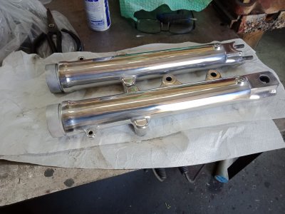
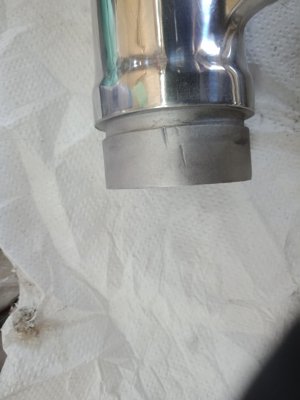
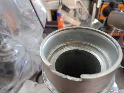
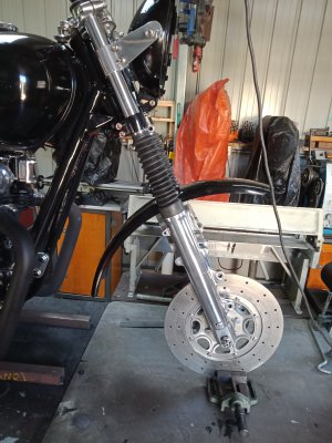
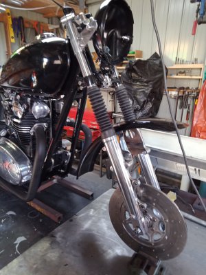
Finally finished off the forks today, right side needed a final polish. These pics show how not to remove fork seals. Some people shouldn't be allowed near bikes, gouging the fork legs like that to get a seal out is criminal..
The damage is actually worse than the pictures show, both legs have deep gouge mark inside and outside the seal housings, one was cracked, but despite blasting the area and using a loupe I couldn't find it. I thought about cutting the top section down to the level of the top of the seal, then turning up an aluminium sleeve with a circlip groove and shrinking it over the seal housing, but, the seals were a damn tight fit and no more aluminium broke off the top. I might still remove the top section down to the level of the seal as the circlip really isn't needed, so tight is the seal fit. The stanchions have a bit of rust on them, hence the gaiters, but, I think the forks look better with them.
 

Attachments

  • fork1.jpg
    fork1.jpg
    2.6 MB · Views: 18
  • fork2.jpg
    fork2.jpg
    2.5 MB · Views: 14
  • fork3.jpg
    fork3.jpg
    2.6 MB · Views: 14
  • fork 4.jpg
    fork 4.jpg
    3.3 MB · Views: 17
  • fork5.jpg
    fork5.jpg
    3.4 MB · Views: 17
  • fork6.jpg
    fork6.jpg
    3.4 MB · Views: 22
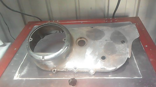
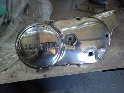
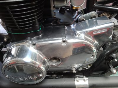
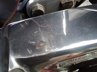
I had another shot at the left side engine cover. No matter how much I polished it before, the aluminium appeared stained. I've tried a nylon fibre wheel before with no luck, so this time I scrubbed it down with wet and dry then polished it, Still the same. It appears there is a fault in the aluminium, I must have scrubbed the aluminium down by at least half a mm, all to no avail. Still nice and shiny, but the staining is really annoying me. Strangely enough, whilst the other aluminium on the bike was in terrible condition, badly pitted and oxidised, nowhere else is staining a problem. It's only in sections rather than the entire cover. Nothing more I can do, so I'll have to hunt around for another cover. Japanese metals have always been of bad quality, too much junk in the casting I'd guess.
Attached Thumbnails
Attached Thumbnails
 

Attachments

  • IMG20210109142254.jpg
    IMG20210109142254.jpg
    2.8 MB · Views: 17
  • IMG20210109143706.jpg
    IMG20210109143706.jpg
    3 MB · Views: 19
  • IMG20210109143658.jpg
    IMG20210109143658.jpg
    2.6 MB · Views: 21
I am getting a very nostalgic feeling with this bike. Looks nice, especially that engine. I just love the UJM style.
 
Back
Top