Ok, code looks good in simulation mode using UCCNC (seeing if Mach was lying to you). As you said it's a series of arc moves so surface finish isn't in the code.
Not the spindle, even though you recently replaced the bearings and might have possibly gotten that wrong. If that were the case you'd be breaking tools or seeing the same problem on straight axis cuts too.
As you say, it's probably not backlash, as I think that causes out of round at the direction changes and not just a general surface finish problem on arcs. On the other hand, backlash-induced surface problems may not show up in a straight axis cut if the axis with slop is snug due to cutter pressure.
So... If not mechanical, and not the code, then what's left is Mach and your motion control hardware. If you want to rule out the VFD making noise and causing the stepper drivers to freak out, stick a fine point pen in the spindle and have it trace on paper with the spindle off. Just do a series of big arc moves and some direction changes. You might be able to see if there's any jittering in the lines.
The pen might be too coarse to see problems, but a scribe on a flat piece of aluminum going down 0.001" might be fine enough if you put a thin layer of dyekem on it first. Another thing to consider would be to see if your Z is oscillating up and down when the VFD is on. Using another flat piece of aluminum or MDF (or something else really flat), run back and forth with the spindle off and a DTI attached to the head and indicating the surface. Then do it again with the spindle on (no tool needed) and see if the needle is bouncing more. I would think that VFD noise would show up on that axis as well as the X/Y.
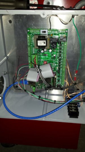
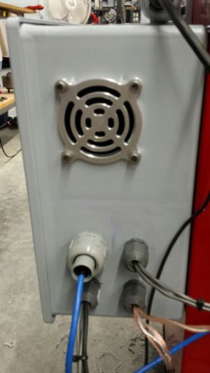
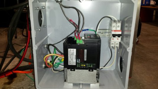
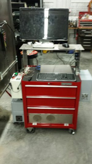
I'm also running a 126 and 107 board, so I don't think there's an issue there with steps making it through your BOB to the drivers. If the 107 board were freaking out, you'd hear the spindle throbbing as the RPM changed. Besides the VFD, motor, 126 & 107, what else have you changed? My guess is most of the wiring is new or different, but you'd obviously know better than I. Have you followed best practices and isolated all of your signal wires from the VFD? Is the VFD in a separate enclosure from the BOB & ESS?
I guess another thing to try would be to make a fairly deep cut in two (or three) depths. Then check the surface with a magnifying glass - if the surface lines line up everywhere, the machine is being commanded (by something) to generate that surface you can completely rule out lost motion or mechanical issues. There's no way noise or mechanical problems would duplicate a surface like that in the exact same location over two or three passes.
Seriously not an expert here, but maybe something will help.
-S


