- Joined
- Aug 22, 2012
- Messages
- 4,273
I'm starting to build a small steam engine of sorts of my own design. Hopefully a double acting uniflow design.
I dont have any drawings because I'm working it out as I go along using what I have available .(and Stealing ideas from everywhere). Its just a learning exercise to see if I can and time is not really a problem. A lot of the fun is in working it out.
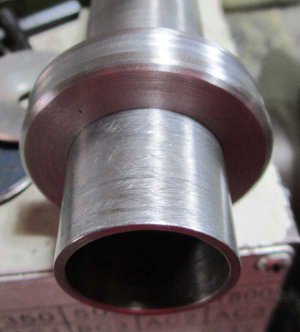
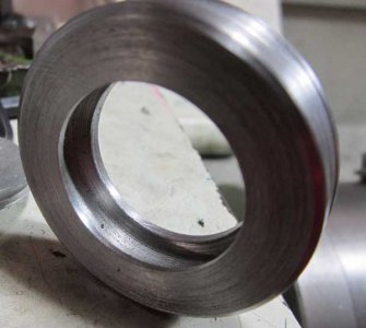
The idea first came about as I was playing around turning some galvanised water pipe then boring it out for as long as I could. The surface finish both inside and out was way better than I expected and my first thought was "this could be the cylinder for a steam engine.
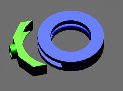
So the next bit of playing was to see if I could mount a 1" square piece of bar and cut a curved surface along its length.
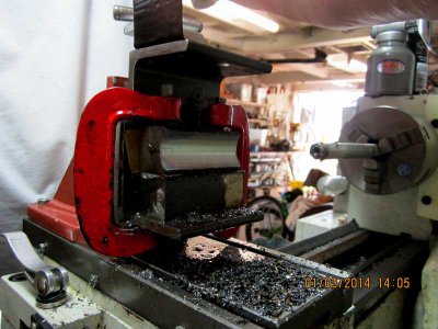
I used the vertical slide I built to make the gear for my reverse tumbler and two small "G" clamps that I cut the screw threads off and filed a 4 flats in the end to tighten them with. (not a lot of room ) I made a couple of passes to set it all up and shimmed the block to get the cut square.
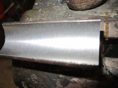
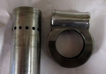
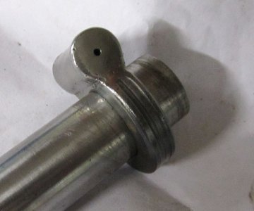
It worked and the surface finish feels smoother than it looks. I dont think I ground the bit to a good profile for this job.
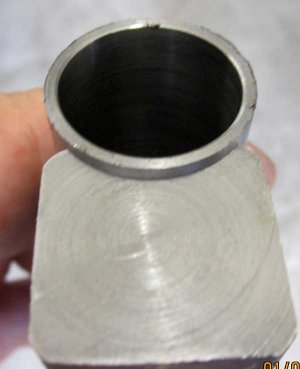
But the end fit looks good to me.
I find it almost impossible to believe it actually worked.
Now I need to stick the block (eventually the valve block/steam chest) to the cylinder.
So the first question is will braze flow through the whole join or will I have to use a softer silver solder.
Thanks.


I dont have any drawings because I'm working it out as I go along using what I have available .(and Stealing ideas from everywhere). Its just a learning exercise to see if I can and time is not really a problem. A lot of the fun is in working it out.
The idea first came about as I was playing around turning some galvanised water pipe then boring it out for as long as I could. The surface finish both inside and out was way better than I expected and my first thought was "this could be the cylinder for a steam engine.
So the next bit of playing was to see if I could mount a 1" square piece of bar and cut a curved surface along its length.

I used the vertical slide I built to make the gear for my reverse tumbler and two small "G" clamps that I cut the screw threads off and filed a 4 flats in the end to tighten them with. (not a lot of room ) I made a couple of passes to set it all up and shimmed the block to get the cut square.

It worked and the surface finish feels smoother than it looks. I dont think I ground the bit to a good profile for this job.

But the end fit looks good to me.
I find it almost impossible to believe it actually worked.
Now I need to stick the block (eventually the valve block/steam chest) to the cylinder.
So the first question is will braze flow through the whole join or will I have to use a softer silver solder.
Thanks.


