Modifying a Harbor Freight 6X26 Knee Mill

Torque Monkey

Registered
Registered
Joined
Nov 28, 2017
Messages
25
I picked up this knee mill on CL about a year ago. The P.O. had already installed the power feed on the X axis, a home made power draw bar and DRO. I have since refit the scales to the table for the X axis of the DRO, remounted the power feed to use the factory trough so I can insert T nuts from both sides of the table now and install a 3 phase motor with a HY VFD and Hall effect tachometer. I posted a few pictures in another thread but I didn’t want to high jack someone else’s thread so I figured I would start one for myself. Plus I have done a bunch of reading on this forum so I guess I shouldn’t be lurking any,ore and try to contribute.

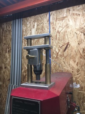
The first thing I would like to share is the power draw bar. It is pretty ingenious. The P.O. to.d me he had copied the idea from somewhere off the internet so I am not really sure where the credit belongs. I can say it doesn’t belong to me as I bought the machine this way, but I can say it works flawlessly. There is no way I would have the patients to change tooling with wrenches, especially since there is no way I know of to lock the spindle from turning.
c3a2406c33544b4b0600bbb2c92caf64.jpg

This system simply uses a butterfly impact that rides on two guides and is spring loaded so when you let go of the handle it pops up out of the way. Depending on what direction you move the handle the impact tightens or loosens the draw bar.


Sent from my iPad using Tapatalk
 
I also posted pictures of the VFD in the other thread but I will post them again here.

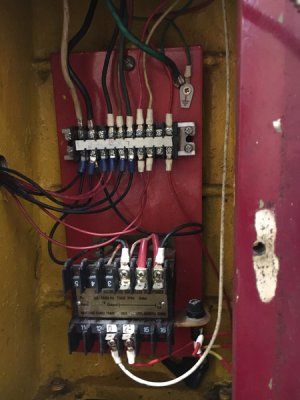
This is what the inside of the machine looked like when I started.

5025eb48ccdf9215145a5eedfa97ae2f.jpg

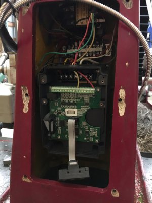
After messing around a bit I discovered that if I removed the top cover of the Haun Yang VFD would fit inside the mill column. I really didn’t want to mount a cabinet on the wall. I was a little concerned with heat but so far it hasn’t been an issue.

This is what it look like once I squeezed everything in.

fd20b0a8f935e29518a6be153ea1c595.jpg


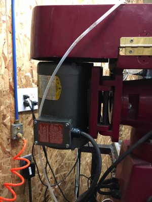
I used a Baldor 1.5 hp motor I scored off CL.

f1f29e0e6184cb55683fd5bf2232ecbe.jpg

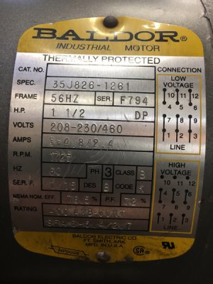
Here is the tag off the motor in case anyone need the frame size. It bolted right into place.

da33a16b18cb609c3f4abeadef774835.jpg

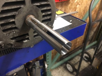
The only issue I had are the shaft size for the original motor was bigger than the 3phase motor. There were both oddball sizes so I could not find an off the shelf solution. I looked at buying a 3step pulley and boring it but all I could find were cheap cast aluminum pulleys that didn’t appear to have enough meat to be bored out. Play A was t make an adapter. Plan B was to make a complete new pulley from steel. Luckily plan A worked.

29638ec5704b9eecc614f5f811565155.jpg


Sent from my iPad using Tapatalk
 
The factory on/off switch failed about 5 months after I got the Mill. The P.O. told me he had to replace it once as well. I tried to find the factory replacement but didn’t have a lot of luck sourcing it I did find it but it wasn’t going to be easy to get again when it failed the third time. As a result I replaced it with a drum switch. This was no longer necessary with the VFD but I still wanted a way to kill power in a hurry so I replaced the drum switch with an E-stop button. I also installed a rocker for fwd/off/ rev and a rocker that is momentary for jog in fwd/off/rev. Lastly there is a potentiometer for speed control and mounted all 4in a plastic box I got at Home Depot.

4bde25ce880493c6823dcebf8931d473.jpg

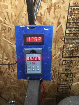
Lastly I just made a quick panel to mount the display for the VFD and tachometer for now. I plan to make an enclosure at some point.

494772614515fafdf70207f9cc0ac47c.jpg

I run the belts on the 1300 RPM setting. Here you can see that at 60hz I have 1353 RPM

10hz = 200rpm
90hz = 2012 rpm

I have the VFD set for 10hz minimum and 90hz maximum, although I have been thinking to bump it up to 120hz as I have been using some 1/8” carbide end mills and would like to spin them a little faster.

With the belts set on the lowest speed setting I have got the spindle rpm down to 20 rpm with enough torque to tap with.

Word of warning, if you are doing this there is some set up to the VFD to be done. It took me a while to figure out if needed I can post my settings but first I would have to go through and write them down as I have no idea where they are at the moment.


Sent from my iPad using Tapatalk
 
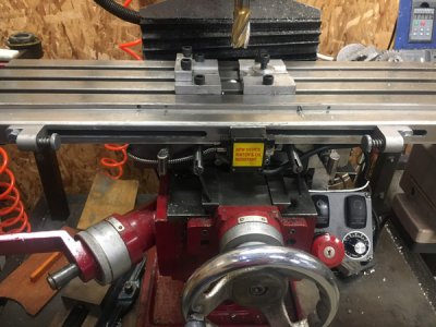
Here is a picture of the X axis scale mounting and limit switch once I redid the whole thing. The stops were fixed but now they are completely adjustable.

6693d47aa300a8e3b1942e9829b82499.jpg

The magnetic scale is mount behind the aluminum cover that holds the stops.

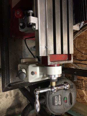
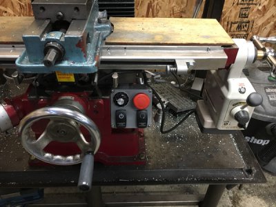
Also here is a picture of the power feed mounted after I mounted the trough back in place. The end of the factory lead screw had to be extended in order for this to be done. An extension was threaded into the end of the lead screw and pinned into place.

ebca497103bf7be8b044466830409185.jpg

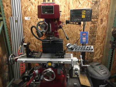
This is how the mill looked before I replaced the drum switch and installed the cast trough and refit the power feed.

84bd5a4951e74deb2104417e00044506.jpg

If any of you want more information please feel free to ask. I am happy to help.


Sent from my iPad using Tapatalk
 
I like the power drawbar, I just might do something like that to mine. I have 80 gal air tank beside the mill.
Thanks for sharing.
 
Nice contribution!
Thanks for sharing it.
-brino
 
very nice, thanks for sharing! I have the Grizzly version of that mill and I'm planning on doing some similar mods :) I have a R8-ER25 collet chuck so rarely loosen the drawbar, but a DRO is very high on the list of things to add. Mine came with an X-axis power feed which I think is awesome. A variable speed motor is next on the list - I have all the parts to put a treadmill motor on there, but I'll keep my eyes open for a 3ph motor locally until then.

Another thing on the list ( :) ) is a spacer to raise the head by 3 1/2 inches to get some more spindle to table room. I have the material and the tools, I now just need the time!
 
Some of those additions ok most are on my list for my enco copy. Already have the butterfly impact 3/8 , even the materials may make the control with tubing for remote location. Planing on the lift also thinking about 6" with the cutouts it should end up between 4-5"" . I have a treadmill to strip in my container , daughter wanted better one. So that motor may work for me.
YUPP thanks and welcome to the site. No wrong questions ,,
 
I LOVE mine, but I must have gotten lucky as mine has a single phase three horsepower motor. I would like power feed though, and this summer, I WILL buy the metal cabinet for it as mine is on a stupidly tall wooden pallet.

The switches must be junk as mine has failed as well

I too need the riser block, but haven't had a problem breaking the draw bar loose without a positive spindle stop, just give the wrench a few good whacks and away I go.

As long as you don't tell anyone it's an Harbor Freight, they'll never know as it looks like all the other Chi-Com machines LOL
 
I’d really like to hear more about these knee mills. I’m always checking hf website for more reviews. With the cost of a Clausing 8520 steadily rising, and these hf mills having what I’d consider technological improvements over them, I very often consider whether or not this model will be the one I buy when the time comes. I hope I’m not instigating a debate over the two. There are plenty of threads on that. But not very much about this hf knee mill. I’d think it would be a real popular option, but sometimes I worry they’ll drop it altogether before I decide to buy, judging by the scant information on the web about them.
 
Back
Top