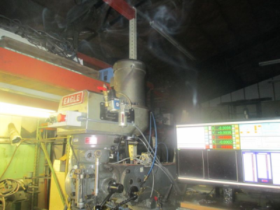
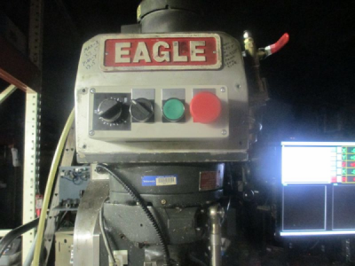
An update a about 1.5 years later. I have a failing bearing in the drive system and it's time to pull the head and replace the bearings.
Click here to go to the top of this thread
https://www.hobby-machinist.com/threads/mill-spindle-direct-drive-conversion.49130/#post-414141
This time rather than pull the mill out its hole, I decided to just pull the head and mount it up on an engine stand to work on it.
@expressline99 built a fixture to pull the head using the table, so I decided to try his method.
https://www.hobby-machinist.com/thr...ly-top-end-now-both-2hp-variable-speed.57208/
So the last job before teardown is to build the fixture out of some scrap pieces.
First pocket the base to fit the pin
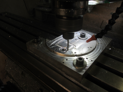
I had the pin sitting on the shelf as you see it, didn't have to do anything to it.

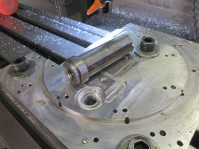
Now stuff it into a 1 inch endmill holder
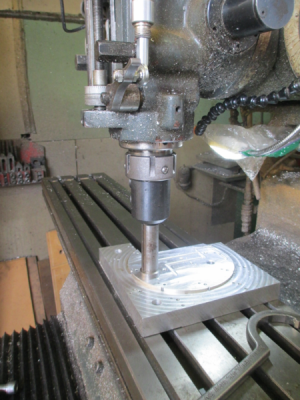
Check alignment and bolt the base to the table
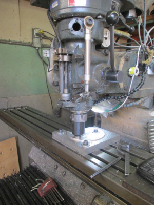
Remove the mounting nuts and carefully start moving the head away from the ram. The weight of the motor hanging on the back of the head was a bit concerning, but as it turned out it was OK. Sag was minimal.
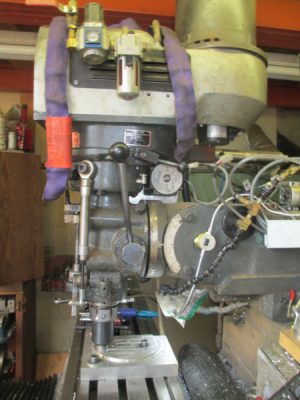
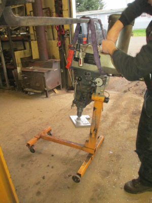
I moved it out just far enough that I could get the forklift fork in the lifting strap. My son was helping with this process, just to get another set of eyes on, and to help balance the head out until we could get the fork in there.
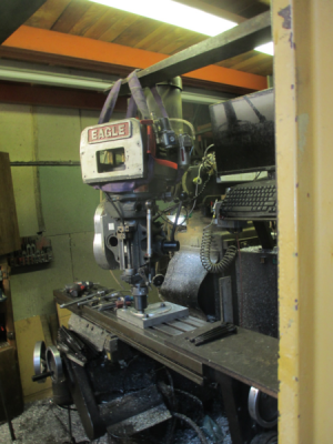
Then unbolt the plate from the table and mount the head on the engine stand. The whole assembly is off of the floor about an inch while removing the motor. With the motor on, the engine stand wanted to tip over backwards. We added about 100lbs of scrap steel to the front of the engine stand to balance it out.
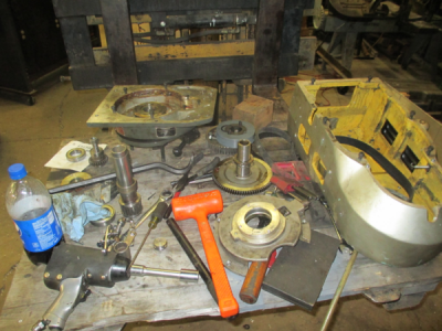
And the head exploded all over the workbench. A forklift makes a great variable height workbench, save my poor old back. Took about an hour to tear it down. I found 2 bad bearings, I'm replacing 4 bearings, the other 2 seem to be fine. BTW, none of the bearings are the spindle bearings, these are all in the drive system.
I should have the new bearings today.
I am also replacing the drive pulleys. Going to overdrive the spindle at 1.5:1. After running a 1.5 years at 1:1, I have found that that is not the correct ratio, so I'm going to speed the spindle up and see how that works. The motor seems to have plenty of power to be able to do this, and it will give a better speed range when in back gear.
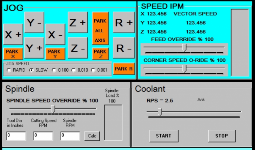
I'm changing from a poly-V belt to a Gates HTD 30mm timing belt setup. The reason for changing to a timing belt drive is that I am writing the software to do rigid tapping and need the motor solidly timed to the spindle. I see a few broken taps in my future while debugging the software and figuring out how to use it.

Stay tuned for more..........

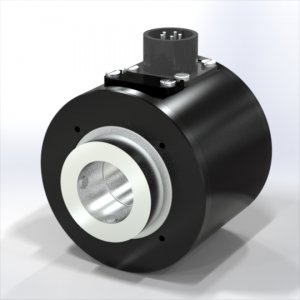
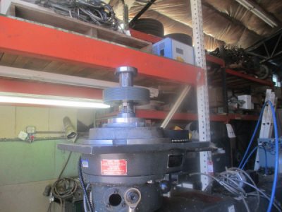
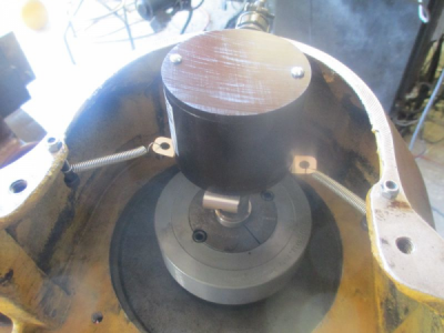
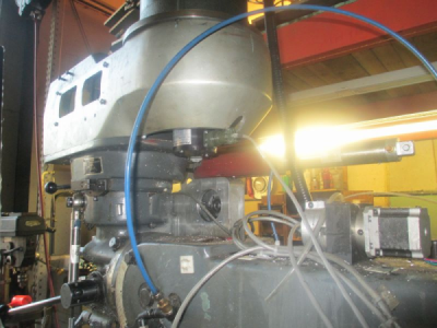
 I cheated a bit on the belt tightening system. There no aligning ring on the bottom of this motor so it can slide around on the mount. So I just put in one bolt, rotated the motor around a bit until the belt was tight and drilled & tapped a new bolt hole for one of the other bolts. If it becomes an issue later, I'll change the mounting system.