Mill Spindle Direct Drive Conversion

I was going to go with a single V-belt, but I was talked out of it by some of the members here, so I went with the poly-V. Glad I did now. Converting yours over should be pretty easy, and about $180 in parts.

Is the Shizouka ready to go?

Almost, just need to finish the tool height comp. And then test run. See if you can get me some G-code for a simple part generated with SolidWorks and HSM or whatever CAM program you are using. Maybe a square with a pocket in it and a hole pattern.

I see your BP is for sale, at that price it's going to fly out of there.
 
Yes just posted the BP. I went with $3k because there is a vari speed on for $4k. I only have about $2k in it and it made me about $12k in 2 years, so doesn't hurt me sell it for that price.
I got tired of waiting for my engineer friend at work to buy it. I need to room and the $$$ wouldn't hurt either. I haven't used it since the day the Kent went online.

I am on vacation this next week so I don't have access to any code files with pocketing right now. And I haven't been working on HSM, been concentrating my efforts on Solidworks. Believe me, learning Solidworks is enough to do at one time.

I think I sent an example of tool height call outs awhile back. I'll see if I can find that.
 
Where did you get your poly belt and parts? I'm seriously considering converting my mill over. I already have motor adjustment, so hopefully if would be easy to just add the new pulleys and belt.
 
http://www.ametric.com/default.aspx?

321495 12J50.2012 ANSI POLY-V PULLEY 2 $65.90 $131.80 OK

998912 2012.35 TAPER BUSHING 35MM BORE 1 $12.11 $12.11 Wrong Size

384213 2012.1-1/16 TAPER BUSHING 1-16" BORE 1 $14.81 $14.81 Wrong Size

781027 300J12 POLY-V BELT 1 $19.37 $19.37 OK, I think

This is what I originally bought, BUT...... the bushing sizes were wrong, but I took a chance based on the Kent sizes. Bushings are cheap, so it was worth it. I didn't know what sizes were actually needed until I tore it down. Took about 2 days to get the correct bushings.
 
I looked up the pulleys and belt, but there is no spec on how wide the pulley is.

Can you measure it and let me know when you have a chance?

I would like to keep my brake, so need to go above the front pulley with the new setup and need to see if the new pulley will clear everything.
 
1.283 thick. You pretty much have a mile of room in there. My shaft sizes are 38mm on the spindle end and 29mm on the motor. Your mileage may vary ;)
 
Yeah I have plenty of room for a pulley that thick. Just couldn't tell at all how thick it was from the pics of it or the belt on their web site.

Now I just have to get that heavy old motor off the top of the mill to measure everything. I've had it off twice since I got it here and dang near dropped it both times.
 
I got a bit more work done today.

I decided the brake was going away so that means some redesign.

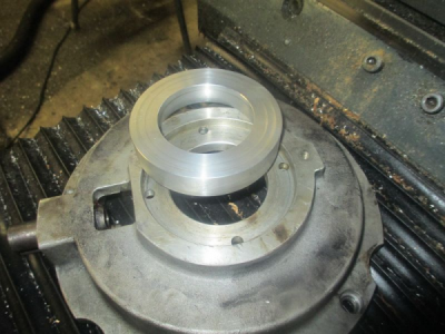
First a new bearing retainer to replace the broken one (see above), also the new design uses a smaller bearing because the old bearing hub was built into the brake drum.

see here for the build on it:
http://www.hobby-machinist.com/threads/work-holding-ideas.34781/#post-415990

Still need to drill the drill & tap the bolt holes.
upload_2016-8-7_16-54-8.png

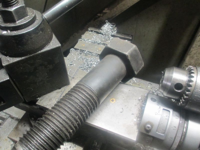
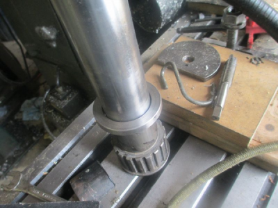
Then I needed a new spacer that sits below the bearing, it also acts as a belt guide for the low speed drive belt. The original was 50mm ID, the new one needs to be 40mm ID. I looked all over the shop for a piece of 2 1/4 inch or so round stock to make the spacer out of, but no luck. But I finally found a 1 1/2 inch grade 8 bolt that is 2 3/16 across the flats, so yeah, I can get a spacer out of that. Nice hard-ish steel, will make a nice spacer:)
upload_2016-8-7_17-1-19.png

I didn't get any pictures, but it didn't take long to make. Grade 8 bolts cut just fine with carbide, even interrupted cuts. I use only the finest AL-8 carbide lathe bits from Harbor Freight, about $2 each.

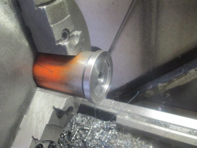
I built another stub arbor and pressed it on to face the other side.
upload_2016-8-7_17-6-32.png

Before pressing onto the shaft.
upload_2016-8-7_17-7-48.png

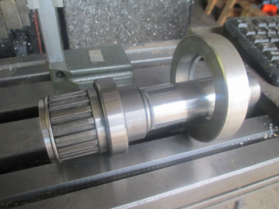
Then I built the spacer that goes between the bearing and the snap ring groove above and pressed the whole assembly together.

Here is the new shaft assembly parts. I still need to drill & tap the bolt holes in the bearing retainer.

upload_2016-8-7_17-13-41.png

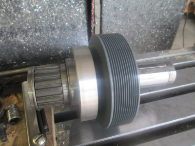
And the rough location of the new pulley

upload_2016-8-7_17-14-50.png

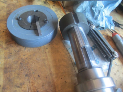
The next steps are to build new shaft keys because the keyways are not standard sizes and don't fit the Taper-Loc bushings so I need step keys. Then bore the Taper-Loc bushing for the motor shaft. Also figure out how to tighten the belt. Oh, and drill & tap the bearing retainer bolt holes:rolleyes:

Stay Tuned..........:)
 
Last edited:
I thought I was going to get the mill back together today, but it was not to be.:(

First thing I did today was to bore the Taper-Loc bushing to fit the motor shaft.

First I just snugged up the set screws just a bit to seat the Taper-Loc bushing in the pulley bore.
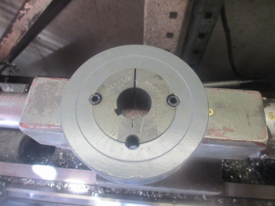
upload_2016-8-11_19-9-50.png

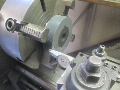
Then I set it up in the 4-jaw. I used a bull nose center to get it sorta close to center, to minimize setup time. It was about 0.005 radial TIR. Note that the pulley is mounted so the small end of the taper is out, so the cutting forces will be against the set screws and not trying to push the bushing deeper into the pulley.
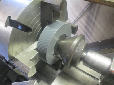
upload_2016-8-11_19-14-42.png

With the jaws snugged up a bit, first indicate the face so the pulley doesn't wobble. Shim as needed, you can see the white piece of paper behind the pulley.
upload_2016-8-11_19-15-43.png

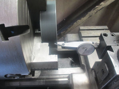
Then indicate the radial runout. I picked the top of one of the ribs as my measuring point. This is a 1.125 bushing and it needs to be 29mm. (1.1403) I chose this bushing because I only needed to increase the bore by 0.015 to fit the motor shaft. It came out fine.
upload_2016-8-11_19-20-22.png

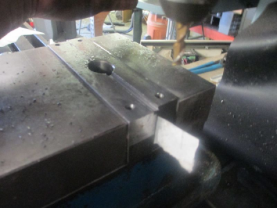
Then I had to make step keys because the keyways in the shafts and bushing are not the same. The shaft keyways are non-standard. So the first order of business was to mount the vice on Alloy's mill and cut a step in the vice soft jaws to hold the key stock. 0.250 wide by 0.100 deep. I closed the jaws up on a pieces of paper in each side just so I could make sure they were closed. I normally keep soft jaws in my vice, they are sacrificial and can be machined as needed for holding odd parts. I normally just leave them in until they are so chopped up so bad that they are no longer useful. These have been used for a number of different setups. These are cold rolled steel, but I also make them out of aluminum.
upload_2016-8-11_19-38-5.png

And the new step keys in place. The one sitting on the pulley doesn't look like it has a step, but trust me it's there. I have to say that Alloy's Shizouka cuts exactly where you tell it to. Nice machine to run. And the 4HP, 40 taper spindle didn't even know it was doing anything with that 1/4 inch end mill in there. BUT...............:mad:
upload_2016-8-11_19-39-51.png


Here is the problem: THE BELT IS TOO SHORT BY 6 INCHES:mad::confused:

I guess I need to go back to school and take a math class again. :rolleyes: When the pulleys are the same size, it's Center to Center distance x 2 plus the circumference of 1 pulley. Somehow I screwed that one up. :confused: There is a new belt on order.:oops:

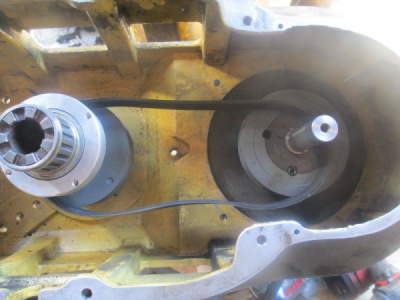
Looking down into the drive housing that is sitting upside down on the bench. Oh, I got the bolt holes drilled and tapped in the new bearing retainer too!
upload_2016-8-11_19-47-8.png

Tomorrow I'll get the new VFD mounted and the new controls hooked up. I can't do any more on the mechanical right now anyway:(
.
.
 
Last edited by a moderator:
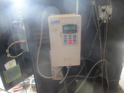
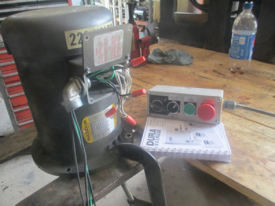
While waiting for the new belt I got the new VFD mounted and wired up. The only reasonable place to mount it was on the back of the electrical cabinet. The old VFD was mounted on the head, but the new one is a bit bigger so I wanted it out of the way. The breaking resistor is below the VFD. Sorry for the crappy picture, the sun was shining in the door.
upload_2016-8-13_23-34-47.png

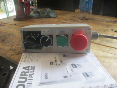
This required building a remote control station to mount on the side of the head. It will be mounted where the old VFD was mounted.
upload_2016-8-13_23-36-19.png

Spent the day tuning the motor and getting rest of the wiring connected in the computer cabinet. I now have all of the wiring in place to have the VFD under full computer control. The VFD has a pulse output that is equivalent to the output frequency, so I connected that to one of the unused encoder inputs on the controller. So I now have the RPM readout on my screen. Getting that to all work correctly was a PITA because the frequency output seems to be unstable and it does not seem to be electrical noise. I had to write some averaging algorithms and take the arithmetical mean averaged over several samples. I may have to build a hardware averaging filter to clean it up, or just put an encoder on the motor. I can get away with taking the speed value from the VFD because the system is direct drive now.

A forklift makes a great temporary motor mount for setting up. :)

upload_2016-8-13_23-51-39.png
 
Back
Top