Mill Spindle Direct Drive Conversion

JimDawson

Global Moderator
Staff member
H-M Lifetime Diamond Member
Joined
Feb 8, 2014
Messages
11,176
Just a little teaser, I got the rest of the parts in today for the vari-drive to direct drive conversion on my mill. I have a bearing failing in the existing drive and I'm getting tired of listening to the noise it makes even with new bearings in it. This conversion will also allow a max speed of 6000 RPM as opposed to the current 4200 RPM.

I'll get started on this in the next few days, I need to get some other work done first and I have a couple of small mill jobs that have to get out the door before I can have it down for a week.;)

So watch this space :grin:
 
Last edited:
I got around to unpacking stuff.

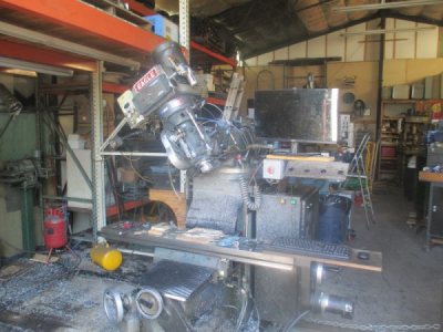
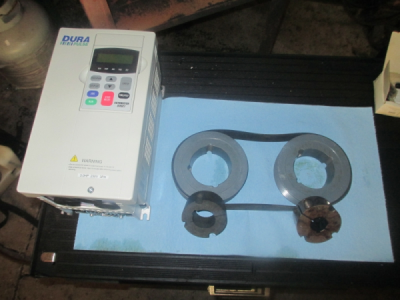
Here are most of the conversion parts. Not a heck of a lot to it. A 3 HP, GS3 sensorless vector VFD, two 5 inch, 12 groove Poly-V pulleys, 35mm Taper-Loc bushing, and a 28mm Taper-Loc, and one 30 inch Poly-V belt. I'll need to build a motor adapter plate so I can have belt adjustment, the existing system just has the motor bolted in place and no way to adjust.

upload_2016-7-29_14-56-15.png
 
Last edited:
Finally getting started

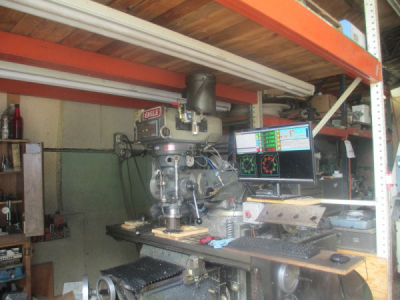
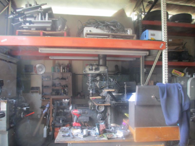
I need to get it out from under the mezzanine first. Running the final job with the original drive

upload_2016-8-3_7-37-28.png

I think I can rotate the head just a bit and remove the lamps from the light fixture and just slide it out.

upload_2016-8-3_7-39-57.png

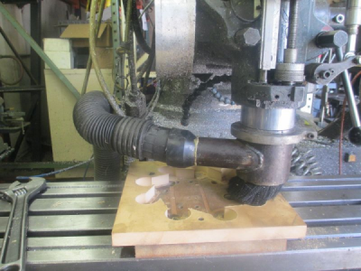
And a picture of my spindle dust collector, works great for working with wood and plastic

upload_2016-8-3_7-41-59.png

More later............
.
.
 
More fun and games.

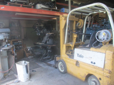
Ready to drag it out
upload_2016-8-3_14-23-0.png

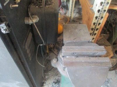
This just cleared the vice with almost an inch to spare :cautious:
upload_2016-8-3_14-24-26.png

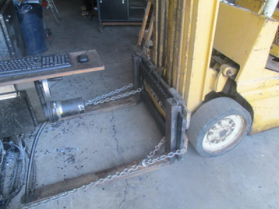
Just ran the chain around the base and pulled. Just over an idle was all it took. Slow and careful. :eek:
upload_2016-8-3_14-26-56.png

And there it is. :)
upload_2016-8-3_14-28-48.png

I didn't get any pictures of pulling the motor, but I just chokered it with a strap, and lifted it out.

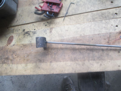
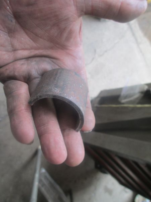
I made this little block a while back to put in the vari-drive pulley to keep it open so it's possible to loosen the belt. Fits right around the shaft. Just a chunk of 1 1/4 pipe.
upload_2016-8-3_14-32-47.png

One small problem with the way the cover is designed, there is no room to get your hand in there to place the block, so I stuck a welding to it for a handle. I'm pretty good at sticking welding rods anyway:D
upload_2016-8-3_14-36-33.png

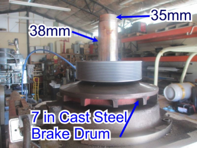
Now for the problems. I have some parts here from Alloy's Kent mill, and the heads look the same from the outside, so I used those to measure for the Taper-Loc bushings. Well that didn't work out so well. It turns out that all mills are not created equal. The Kent driven shaft is 35mm over it's entire length. Mine is 38mm except for the top bearing area. The good news is that 38mm is a standard Taper-Loc bore. So no problem there. It will be on order this afternoon!

The other thing I failed to concider is the 7 inch cast steel lower pulley half, which is also the brake drum. I sized the new pulleys to take the motor rated speed of 6,000 RPM, but that 7 inch pulley half is only going to take 4250 RPM. Can you say cast steel grenade :eek::eek:. Now what to do????? I could just limit the speed to 4250, or take the cast pulley off and not have a brake, or maybe make a new brake drum out of some 4350 so it would take the speed. Operating without a friction brake would not be a terrible thing, it only gets used for tool changes, never for stopping the spindle. Dropping it in to back gear gives plenty of resistance to do tool changes. Decisions decisions.:oops:

This about where the new driven pulley will sit.
upload_2016-8-3_14-49-55.png

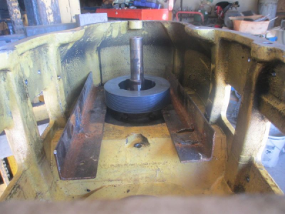
Here is about where the motor pulley will sit in the housing. The good news is the the pulleys will line up just fine with no modifications to anything. BUT..............I ran into another small problem. :confused: The Kent mill motor shaft seemed to be 28 mm (1.102) over the entire length, a little hard to measure because is was torn up so bad. So I ordered a 28mm bore Taper-Loc. Well it turns out that the design of mine is completely different. In the picture you can see the step in the motor shaft, 23mm (0.906) then steps up to 29mm (1.142) just above (actually below, it's upside down on the bench) the pulley, and of course stock Taper-Loc bore sizes are 28 or 30 mm, no 29 mm:mad: I guess I'll bore the bushing out to 29mm and make a special key or maybe turn the motor shaft to 28mm
upload_2016-8-3_15-24-9.png

Next I have to figure out how to tighten the belt. With the vari-drive, the motor is just bolted in place with no provision for adjustment. I think I can get away with just slotting the motor base and call it good. I won't know for sure until I'm able to install the pulleys and see how much travel I need in the motor.

More later......
.
.
 
The other thing I failed to concider is the 7 inch cast steel lower pulley half, which is also the brake drum. I sized the new pulleys to take the motor rated speed of 6,000 RPM, but that 7 inch pulley half is only going to take 4250 RPM.

After running some calculations on this I have decided to go ahead and run it as is.

upload_2016-8-4_10-26-9.png
http://keisan.casio.com/exec/system/1271292951

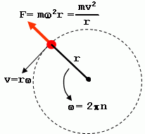
The centrifugal force on the extreme outer rim will be about 10,000lb max at 6000 RPM. So assuming that the cast steel has a conservative yield strength of 30,000 PSI, I should have a pretty good safety factor. This is kind of a back of the envelope calculation, to actually do it correctly it should be an integral calculus problem taking into account the cross section area of the part but I'm to lazy to write a program to do the calculation.

Also concider that automotive flywheels and vibration dampers and other large rotating parts turn well over 6000 RPM on occasion and don't blow up (most of the time) :cautious:

Feel free to jump in here and point out any errors in my calculation;)
 
Well another problem rears it's ugly head. I noticed some looseness in what I thought was in the lower driven shaft support bearing, as it turns out the bearing spun on the inner brake hub and that's what was loose. The bearing seems fine, but I'm going to replace it. For about $10-$15 it's not worth taking a chance on.

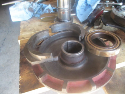
Worse than that, the two piece bearing retainer you see in the picture used to be a one piece bearing retainer.:mad: It broke when I was trying to get the bearing off of the brake drum hub. The bearing was stuck hard just above the spun area. Normally these are just a very light press fit. The genius that designed it decided to make it out of cast. The new one will be steel. The good news is that I have Alloy's Shizouka here to make a new one, and I need to test it anyway.

upload_2016-8-4_14-16-27.png

Then the question is: Do I sleeve the hub on the brake drum, or do I just eliminate it altogether and build a spacer to take it's place. o_O There is not a lot of meat (about 2.5mm) there at the keyway so I'm reluctant to remove much material to sleeve it because it's cast also. I need to think about this for awhile. I'll do that while I'm drawing up a new bearing retainer. :blue:
 
After thinking about it a bit, I think I figured out why the bearing spun on the hub. Last time I rebuilt the head, I bought inexpensive bearings off of the Internet for the drive components (not the spindle bearings, went top of the line on those).

When I took this apart I noticed that there was grease oozing out of the bearing, black gooey, tar like grease and this is at 90° F. And a lot of it, probably a solid mass when it's cold in the shop. Even warming the spindle up before cranking it up to working speed would not thin this grease out. No way to see what was in the bearing when I got it because it's a shielded bearing. Never seen a gooey stuff like this in anything but very low speed bearings in heavy industrial equipment or bull gear grease for things like excavator rotators.:confused:

I never gave much thought to bearing grease before for utility applications in normal speed ranges. I will be getting a new bearing from a local vendor and a known quality brand, probably SKF. I learned my lesson, I'm done with cheap bearings.:mad:
 
Back
Top