Now, Spindle Bearings are interesting one. They need to run very accurate, but due to manufacturing tolerances every bearing has some inner clearance to accommodate housing and shaft size tolerances. To cancel all of that, usually spindle bearings has some kind of adjusting mechanism. On my machine it is done by taper inner race, so when I tighten nut that holds inner race on shaft, it pushes it up, expanding inner race to the size needed to cancel all inner tolerances. Who ever need more information about this subject I strongly recommend this text written by professionals:

highspeedtechnologies.com
or this discussion from other forum:
Hello Couple of weeks ago i purchased a DM4400 running the old skip controller. I gave it power and all the axis would home perfectly. I was able to re
www.cnczone.com
or this recommendations from SKF:

www.skf.com

www.skf.com
Now, this is how I was done it:
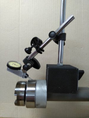
On first picture my initial setup for reference can be seen, a two micron dial test indicator on mag base touching an outer race, hold on position by mag base stick to shaft. Grey ring between bearing and mag base is ring made from aluminum just to prevent bearing outer race to tilt during measuring. Inner race was just pulled on shat by hand as far as it can go, without knocking it or any force. How many inner tolerance I have can be seen on this video:
I move outer race sliding perpendicular to shaft axis along aluminum ring without any force. Measuring says 24 microns. After I was mount outer race in Housing, I was again measure clearance. This time mag base is mounted on Quill, aluminum ring was removed. Guiding of shaft was accomplished by back bearing and inner race was on the same place. Measuring was done by moving shaft up and down instead of moving outer race as on previous video. Result is shown here:
Measuring says 22 microns. Did I mention that outer race has loose fit in Housing? Nut has 1mm pitch, and according to SKF equation for Tightening angle Alpha are: 360*18*C/(1000*P) where 18 is constant base on Spindle wall thickness, C is measured clearance (here 22 microns plus recommended preload, here 2 to 5 microns) and P is Tightening Nut Thread Pitch, so after some math I get 168 DEG. Third video shows clearance after some initial tightening...
After I was tightened it to about 120 DEG I was decided to stop because bearing has preload and I do not want to overtighten bearing. After all, I can tighten it later if there is need for that. If it is overtightened it will heat more then acceptable. Heating is a matter of grease also.
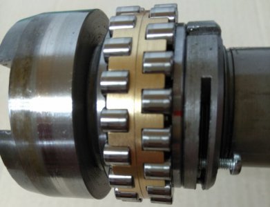
On second picture new ball bearing mounted but not yet tightened with tightening nut and red mark for tightening angle measuring can be seen.
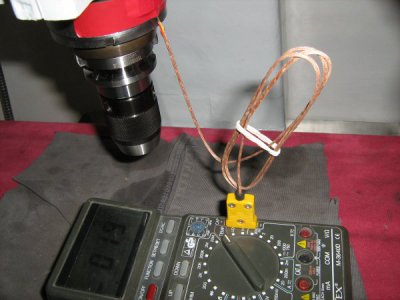
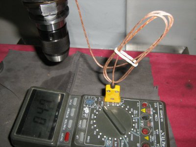
Proper procedure calls for bearing running in during which process temperature rise has to be measured. So, I put thermo couple with some silicone grease used for transistor mounting on heat sink for temperature transfer and let spindle to run, from slowest to fastest speed. After about hour of running, forward and revers the temperature rice from 19 Celsius to 47 Celsius.
This is result I am satisfied with.

