Marvel Draw Cut Saw No 1 not a restoration (more of a resurrection)

Shootymacshootface

I make little metal out of big metal.
Registered
Joined
Mar 17, 2018
Messages
1,400
Howdy folks
I picked this up off of the Craigslist a few weeks ago. I think that this will be a fun winter project. I got a few other things in the shop finished up, so I could get started on this.
20201117_213234.jpgScreenshot_20201117-180239_Samsung Internet.jpgScreenshot_20201117-180223_Samsung Internet.jpgScreenshot_20201118-111228_Samsung Internet.jpgScreenshot_20201117-225430_Samsung Internet.jpg
 
Last edited:
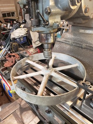
So far I have got the the inside of the large pulley cleaned up.
20201206_225940.jpg
It needs a new shaft, so I turned one to fit the new pulley hole for a perfect slip fit. It took me a couple tries to get it the way I wanted it, not like youtube.
I have some Torrington bearings that will be pressed into the frame. I'm pretty sure that I want to do this next so that I can test fit a turned down dummy shaft to get my final dimension on the new shaft.
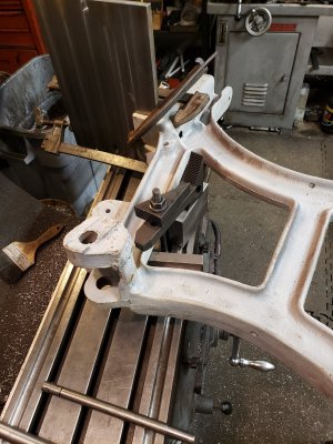
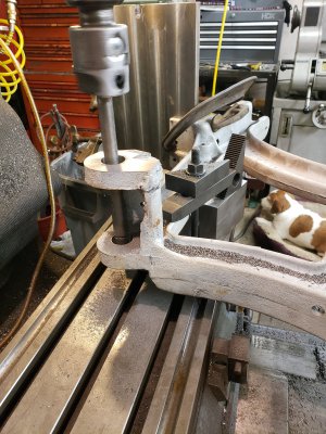
I set the frame up on my mill last night. I plan to line bore the holes. I referenced my set up off of the cast in vise backjaw and table.
What to you guys think of this set up?
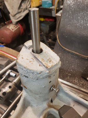
Also there is a wedge on the frame for the line shaft clutch. I am thinking of milling this to have a flat surface for the big pulley to ride against.
20201211_065747.jpg
20201211_065734.jpg
I haven't cut anything on this yet. I want to take it slow so that I don't turn this to scrap!
 
If Torrington bearings mean needle bearings, they do not do well with soft shaft, or should I say that a soft shaft does not do well with needle bearings; a bronze bushing would be appropriate.
 
Thanks benmychree, perhaps I will have to harden it. I will also be making a grease passage in the shaft. There will be 4 bearings total. I have to make a swinging v-block guide from scratch. That will pivot on the spinning shaft. That should be interesting .
If all else fails, I could go to bronze, maybe I'll overshoot the holes on the frame and have to change my plans. I already have the bearings.
Thank you!
 
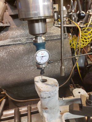
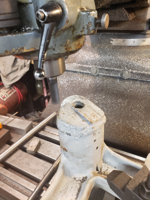
I checked the hole alignment, since there was a repair here. It is out by .010 - .015", but I don't think that it matters because everything I do in this area will be based off of the cast in back jaw and table.
20201212_135719.jpg
The holes are actually quite round.
20201212_141456.jpg
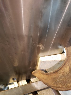
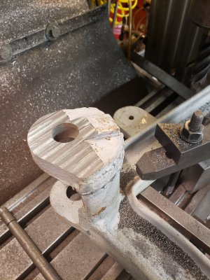
I milled the clutch wedge flat enough for the big pulley to ride against. I'll probably have to make some shims to space the pully out to align with the drive pulley. I'm not crazy about the striped finish. I will try a fly cutter. I hope this tall casting won't bounce when the cutter engages the material.
20201212_142948.jpg20201212_144917.jpg
 
Luckily, I had this old boring bar and just had to turn the end down to .5 to fit my boring head. There was lots of chatter because of its length, but I found that slowing the speed and feed way down helped a lot. The spec. for the bearings say the hole needs to be between .9995 and 1.0. I'm at .988 right now, so its time to do some test spring passes to see what I have to do to hit my number.
20201214_231635.jpg
 
I was looking up the specs for my bearings, and they actually do (not that I doubted benmychree for a second) specify the hardness for the shaft. The shaft is also the inner bearing race.
Screenshot_20201213-225100_Drive.jpgScreenshot_20201213-230022_Drive.jpgScreenshot_20201213-225753_Drive.jpg
 
Back
Top