[Shaper] Little problem with shaper table

Ron,
That collar is only pinned to the outer tube isnt it? Not right through the sleeve and to the inner threaded section?
From what I am seeing and surmising, cranking the handle to move the table up and down would, by a gear drive inside the table, rotate the inner threaded rod. This would, 1) screw itself in and out of the collar, and 2), because it extends through the outer tube without touching, except at the threaded sleeve, turn a gear drive located on the bottom of the inner threaded rod that is connected to the outer tube, thus rotating the outer tube and also screwing itself in and out of the base of the machine:phew:
This is all starting to sound very involved :panic: but I think it will be a simple drive at the bottom that is broken off. Best comparison I can think of is like a rear axle differential, using a spider gear set up to transfer the drive from the inner shaft to the outer tube:dunno:

Cheers Phil
 
Man youve got me going now! Brain in overdrive:huh:
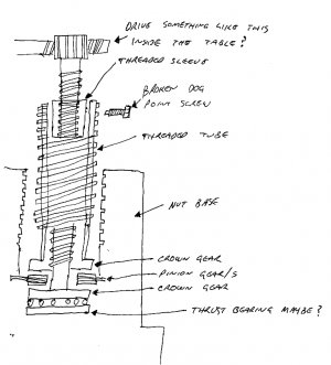
Thinking some more, (not always a good thing), does this sketch, (dont laugh,... its late) make any sense?
pic.jpg
Probably a worm and wheel drive to the top of the shaft.
Rotating the shaft causes it to screw itself out of the collar, whilst at the same time via a crown gear at the base driving through a pinion, (or 2), another crown gear attached to the threaded tube. Which in turn screws itself up and out of the base/nut.
I think you have got a broken drive at the bottom of the threaded tube. Maybe where that broken Vee piece is, looks like it has a drilled hole at the apex of the vee? And that was where the crown gear was pinned to the tube.

..........did you ever get the feeling that its time to shut up and let people only think your a fool, instead of opening your mouth and proving it..............:shush:

Cheers Phil

pic.jpg
 
Ron,

Apparently the Queen City shaper isn't the only one to use this type of mechanism. I found an owners manual for a Steptoe shaper (made right down the road from me in Holland Michigan) that shows the same arrangement. It is a telescoping screw assembly that allows the mechanism to fit in the limited space available under the table. It works as follows: The inner screw is attached to the elevation crank and does the initial lifting of the table. When it runs out of travel, a collar pinned to the end of it contacts the nut forcing the outer screw to rotate and lift the table the rest of the way. It's a mystery to me how the collar got broken off, unless maybe someone tried to lift the shaper by the table and sheared the pin off that way. Hopefully this will get you back on track.

Your set-up isn't exactly the same as this one, but the principle is the same.

BTW, I uploaded the entire manual to the download section. It appears quite similar to yours so you may want to grab a copy.

Tom
 
Last edited by a moderator:
Could someone tell me where the download section is ? Thanks Keith.

Keith,

As soon as you hit 20 posts, the download section will become available. It's just a little something done here to encourage participation.

Tom
 
If you have a lathe make it new and better. That's what I would do.
 
Could the damage on the bottom of the outer thread have been caused earlier and someone turned it over and redrilled it to fix the problem. If that is so then it is not pinned to anything on the bottom. the gouge on the nut looks to me like it matches the damage on the bottom of the outer tube.
 
First of all, guys, thanks for getting involved with helping me figure this thing out. I really appreciate the help you are giving. Tom, I'll definitely look that up in the downloads area. That could be a great help.

Both of the setup shown by Phil and Tom come close but don't get us home all the way.

I was able to learn a bit more about the nut area today and found a set screw that will allow me to pull it. That's the good news. The "bad" news is that there is nothing more to be found out concerning the nut, what the sleeve might have been pinned to or much else. There is nothing else there besides the nut. The nut itself has about two inches of acme thread which transitions into a smooth "skirt" for a couple more. At least that's the best I can tell until I get it pulled (I'll have a go with an impact driver tomorrow).

I took a few more pics and made a drawing to try and make it as clear as possible what I've got to work with.


Here you can see how much room there is in the sleeve as well as the smooth finish inside.


This, of course, is peering down the nut. If the view were at more of an angle you would see the concrete beneath it. Not much going on there.


This was just a full length shot to show just how hollow the sleeve is inside as the screw itself is solidly in place.

To sum things up I made a quick drawing of the parts that are present and there relationship to each other. Please ignore the errors in scale. :p


As I tried to show in this drawing the fitting that the screw comes out of is the same outer diameter as the inner diameter of the top of the sleeve. There is also a flange at the top that is the same diameter as the outer diameter of the threaded sleeve. I probed the sleeve with my finger to find out that it is thicker at either end than it is along it's length.

Now, given time to go over things and studying the provided drawings from Phil and Tom in great detail, I have a theory (an no it's not a sign of the apocalypse :rolleyes::biggrin:).

When I received the shaper it appeared that the outer sleeve was "pinned" to the fitting that the screw comes out of. That would preclude the sleeve and the screw from moving independently of each other which does not make sense to me. That would basically limit the travel of the table to the few inches that the sleeve would travel in the nut.

I theorize that the lift mechanism became inoperable at some point (I would guess having something to do with section missing from the bottom of the sleeve). Some "rocket scientist", instead of fixing it properly, decided to make the table lift partially functional by pinning the sleeve to the inner screw (the fitting). All of which resulted in the hogged out hole as well as the nasty gouge in the fitting.

The trick at this point is to "reverse-engineer" this thing to get full travel out of the table. This could be interesting. :biggrin:

That's where we're at.

-Ron
 
Last edited by a moderator:
Assuming that both are left hand, same pitch, I have a vague idea that one turns (the easier one, the smaller one) until it runs out of travel, and somehow locks up and starts to turn the larger one to increase the ultimate overall length. On the smaller screw, do the threads run off the end, or does it (or perhaps did it) shoulder out? Or perhaps the dog point is timed to lock in at a certain length? It's hard to say for sure that you even have all the pieces for sure at this point.
 
Thats exactly the way my great big no name drill press table works. Thinking hydralics wouldnt be a
bad idea either always a way out.
 
Back
Top