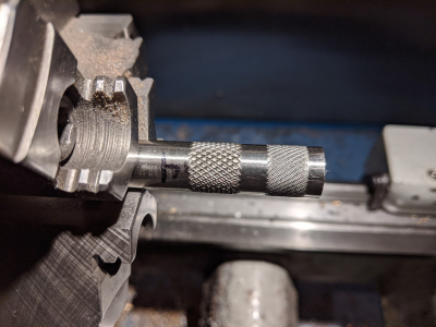
Knurling tool build

One knurling project could be making a nice 2 inch or so knob to fit the tightening bolt. Would be nice to be able to tighten it with no tool.

Countersink the bolt head into the knob, thread it and put another nut against it to hold it in place.
 
I already thought about that! Thanks!
Robert
 
My toy mill is not going to be able to cut that slot. Hence plan B. Plus that is a lot of steel to subtract.
I just made a test joint using nickel silver. It flows at a much lower temp and made a very solid joint. That may be the way to go. My brazing rod is coated with blue flux. Is there a specific flux I could/should pifut inside the joint in addition?
Robert
Not sure if anyone chimed in but powdered borax is the about the best for brass . You dont need high price named borax. And i think your design will work great as a two jaw knurl.
 
  • Like
Reactions: rwm
I used this setup to drill and bore the larger holes:

View attachment 316922

I decided to reduce the threaded pivot hole to 5/8". That should be plenty large. I had about 1/8" clearance on the swing.

Here's where we are.

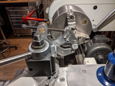
View attachment 316924

You may notice I used DTMS welding on the wings. This causes a lot less distortion than TIG.

I have a plan to propose; back to the axles: One issue is the arm spacing needs to be fairly accurate for the knurl wheels to run properly. The wheels are 0.375 wide. I would like the arm spacing to be about 0.378. The only way I can see to effectively accomplish this it to use an axle with a shoulder that abuts the arms. My plan is to use a hollow axle. It would be 0.250 diameter and 0.378 wide. It would be drilled to accept a #8 screw and clamped in place by that screw between the arms. I would like to use a #10 but that would leave the wall thickness of the axle at about 0.030" which I don't feel good about. I don't see a #8 screw shearing under this load? I could use O1 tool steel if people think a hardened axle is important? I could also make spare axles easily. I am open to other suggestions.

I am excited to grind the tabs off the arms and separate the two pieces!

Robert
Ever thought of dowel pins there hardened and should hold up. Just a thought
 
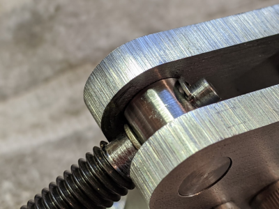
Detail of upper pivot. The screw is turned down to 3/16" and there is a C clip retaining it.
1584904652122.png
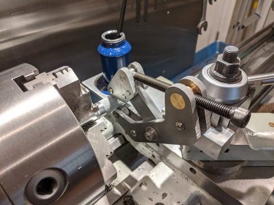
Mounted:
1584904745843.png

1584904758959.png

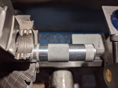
First aluminum:
1584904783355.png

Then 304 SS:
1584904843433.png
You can see, one did not work so well. One of the wheels double tracked?

Robert
 
Last edited:
The first set is beautiful! Isn't it true that there is one perfect diameter for a given pitch of the knurl wheels? Maybe on the second set the work was not the correct diameter?
 
The first set is beautiful! Isn't it true that there is one perfect diameter for a given pitch of the knurl wheels? Maybe on the second set the work was not the correct diameter?
Correct (sort of.) There are multiple diameters that a wheel can run perfectly based on the knurl pitch. But not all diameters. It can be calculated but trial and error works too. I used two different pitches on the SS. Only one worked correctly.
I am thinking the best way to do this would be to mount the tool on the back side of the cross slide on a rigid mount. Then you could see the action better and the tool would be more rigid than in the QCTP.
Robert
 
Last edited:
I see.

Mounting to the backside sounds like a nice idea, for viewing purposes.
 
Do you think the steel one just needed more pressure to make the points form up?
 
Probably so. I cranked down on it pretty hard. It is really hard to see the action with a front mounted tool. I could have made more passes to get deeper. The incomplete knurl actually looks and feels pretty good in person.
Robert
 
Back
Top