The other Rods and their Crank Pins
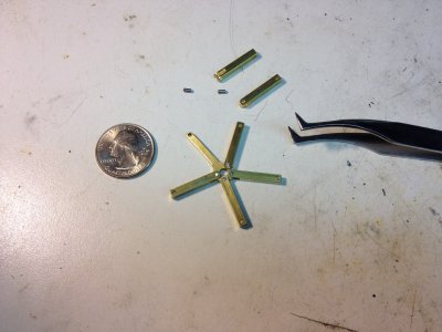
The picture above shows a test fitting of the connecting rods assembly. There are little tiny 1/16" diameter by 1/8" long crank pins to attach the (slave?) connecting rods to the master connecting rod.
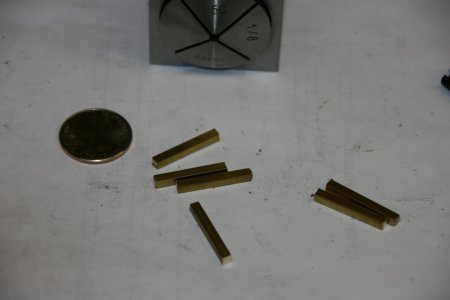
The slave rods are made from 1/8" Square Brass (360). I cut them a little long with the band saw. Then with the lathe I finished the ends and brought them to final length using the 5C collet shown above with a stop in it.
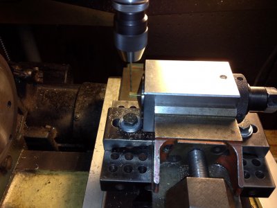
Well, I had originally thought about doing these parts with the pistons... Then I thought, no, I should use a vise... Well, couldn't figure out how to hold these little boogers in the same place in any of the vises I have. So, back to Plan A. Virtually the same setup as the pistons all over again <sigh>
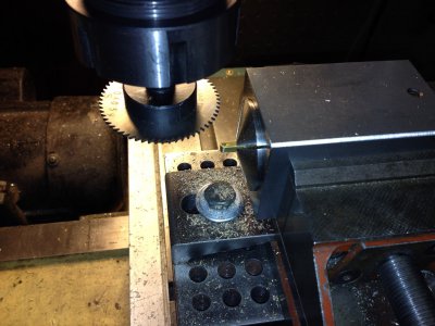
Above I'm getting ready to saw the slot where the Rod fits over the Master Rod. I carefully put the radius on that end of the part with the 1" sanding belt. (I'm glad I had a few extra).
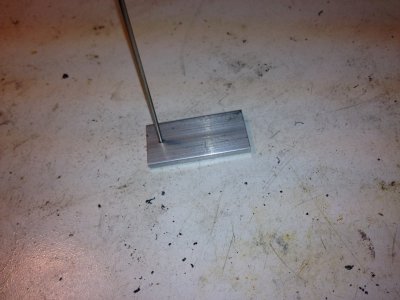
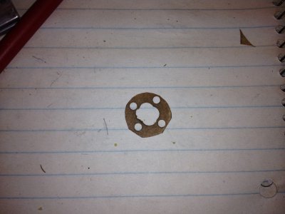
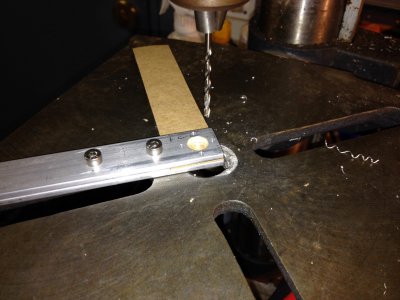
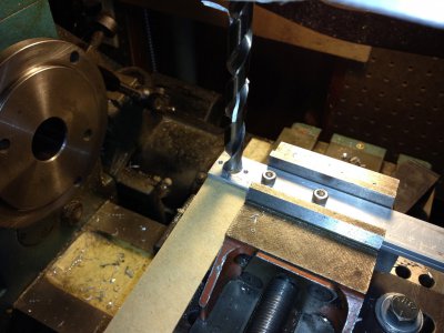
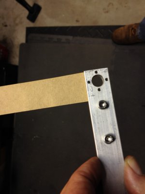
I made the little connecting rods from some 1/16" diameter 303 stainless round. If you look above where I made the pistons you will see the same piece of aluminum that I used to line up the hole versus the slot in the pistons. This piece of aluminum is 1/8" thick. I reamed the hole in it with a 1/16" ream (it had previously been .0615"). Did you know aluminum spelled backwards is pronounced muni mu la ?
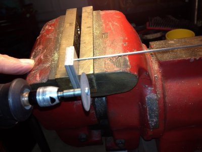
Then I backed up that piece of aluminum with another and clamped it it the vise. While pressing and turning the ss rod into the hole, I sawed it off with a cutting wheel in the Dremel.
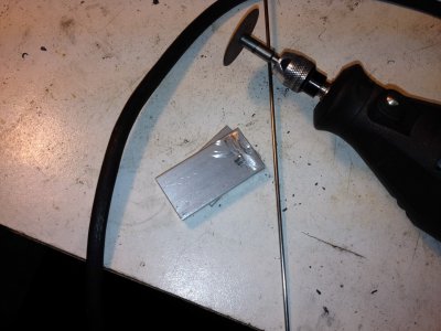
Do you see the part in the fixture above? I don't either, so I made some extras. At least one of them is somewhere on the floor of my shop. I was thinking how in the heck am I going to deburr these little rascals. I decided NOT to. Cutting them off this way did leave a very little "head" on them like a little rivet, but the top of the rivet was smooth. The little head keeps the pin from falling through the rod, easing the assembly.
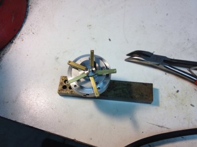
Above I trial assembled all the rods and put them on the crank. Boy am I glad I did! I had not sufficiently rounded the lower end of some of the slave rods, and they would not wag back and forth and didn't want to spin around the master crank pin. So more radiusing and deburring was performed. Assembling like this shown above was a piece of cake compared to later when I had to assemble it in the crankcase, with the cylinders mounted and the pistons on the top of the rods. That was like assembling a ship in a bottle. Still, I really think this is a clever clever design!

This is my "special" cat, he gets to spend a lot of time in the house. He was a "gift" from my daughter. The way you read "gift" is, he came home from college with her, but then he never left...
Several more easy things to do but the engine is getting close to being done now and I am Jonesing to see it running.
Thanks for looking over this.
best regards,
Dave


