-
Welcome back Guest! Did you know you can mentor other members here at H-M? If not, please check out our Relaunch of Hobby Machinist Mentoring Program!
You are using an out of date browser. It may not display this or other websites correctly.
You should upgrade or use an alternative browser.
You should upgrade or use an alternative browser.
I'll just take this one part off...
- Thread starter David Pollard
- Start date
David.
I also have a broken 10F-11 Gear Case Assembly. Price at Clausing's is $113.85 + Freight.
Try Jolene Olds, jolds@glausingc.com
I am also restoring a Ferguson Multi-Purpose Blade with a broken locking mechanism.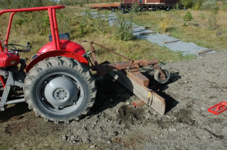
I hava a few brochures and a Parts list to E-mail if you like.
It's a small world. I live in Iceland in the North Atlantic. Far away with the same problems and tasks.
Atli

I also have a broken 10F-11 Gear Case Assembly. Price at Clausing's is $113.85 + Freight.
Try Jolene Olds, jolds@glausingc.com
I am also restoring a Ferguson Multi-Purpose Blade with a broken locking mechanism.

I hava a few brochures and a Parts list to E-mail if you like.
It's a small world. I live in Iceland in the North Atlantic. Far away with the same problems and tasks.
Atli

Last edited:
- Joined
- Feb 7, 2013
- Messages
- 792
Terry,
I have had those two bolts out of the lead screw bracket already when I had the apron off.
Now I'm more interested about fixing or replacing those two stripped nuts and couldn't tell if there was some secret to getting them off.
Iron Man,
when you say replace them nuts with a "collar with a setscrew" did you make a round cylinder to go over the end of the lead screw, drill and tap a hole in the side of it and clamp it down on the top of 1/2" thread?
I suppose I could just make a flat on the 1/2" lead screw thread for the set screw to land on.
I'm sure I'll come up with something.
Yes that is what I did with mine the nuts are not a very good design you can run without them the lead screw is trapped in there its not going anywhere.
- Joined
- Sep 20, 2012
- Messages
- 560
I suppose I could just make a flat on the 1/2" lead screw thread for the set screw to land on.
I'm sure I'll come up with something.
While you're making some sort of fix you might think of making the piece over long so it could be fitted with a wheel at a later time, these are surprisingly useful for fine adjustment of the carriage when milling and such tricky stuff...
http://www.hobby-machinist.com/showthread.php/15175-Lead-Screw-Hand-Wheel
Bernard
- Joined
- Nov 24, 2017
- Messages
- 64
Hi Atli,
My Blade had a locking mechanism on the end of the boom with springs and linkages and it looked like it has been smashed and welded up a few times. I didn't feel like repeating someone else's mistakes. I pulled it apart as much as I could so it wasn't so heavy to work with. Then drilled a 1" hole sraight through the boom directly above the locking gear but on the forward side if the main pivot shaft. I then used a standard 1" tractor pin straight through the hole. I ended up filling the gear tooth shape on the end of the pin as they arn't hardened. This way it will be the weakest link and I'f I shear it off it shouldn't damage anything else. I can just replace it.
Good luck sorting yours out.
David
- Joined
- Jan 28, 2011
- Messages
- 3,584
Just to add some information.
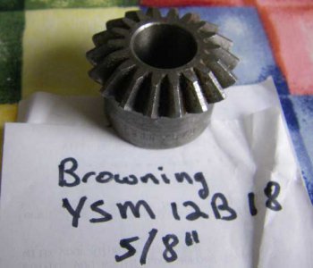
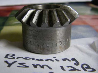
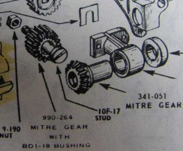
The bevel gears are standard in form. I used the Browning YSM12B18 5/8" gear to make a new 990-264 Mitre Gear. This is the gear that has the crossfeed drive gear as part of of it. It takes the rotation from the 341-051 Mitre gear ( Are the new versions steel from Clausings? The two new ones I had were. ) on the lead screw and transfers it to the gear on the crossfead gear 10F-33. I used the Browning gear and turned the exterior down a bit and had a new straight gear and openned the center up to make a press fit onto the bevel gear. Also inserted a oilite bushing and cut the end of the gear to properly fit the stud 10F-17. I still have a couple of the Browning gears on hand and have included a picture of how I received them from Browning. With some reverse engineering either one of the mitre gears can be made up using this YSM12B18 gear. Hopefully people how are far away from Clausings can find the equivelent gears locally if required.
Pierre


- Joined
- Feb 7, 2013
- Messages
- 792
Just to add some information.
The bevel gears are standard in form. I used the Browning YSM12B18 5/8" gear to make a new 990-264 Mitre Gear. This is the gear that has the crossfeed drive gear as part of of it. It takes the rotation from the 341-051 Mitre gear ( Are the new versions steel from Clausings? The two new ones I had were. ) on the lead screw and transfers it to the gear on the crossfead gear 10F-33. I used the Browning gear and turned the exterior down a bit and had a new straight gear and openned the center up to make a press fit onto the bevel gear. Also inserted a oilite bushing and cut the end of the gear to properly fit the stud 10F-17. I still have a couple of the Browning gears on hand and have included a picture of how I received them from Browning. With some reverse engineering either one of the mitre gears can be made up using this YSM12B18 gear. Hopefully people how are far away from Clausings can find the equivelent gears locally if required.
Pierre
Good info a better fix than original.. Ray
- Joined
- Nov 24, 2017
- Messages
- 64
Hello Again,
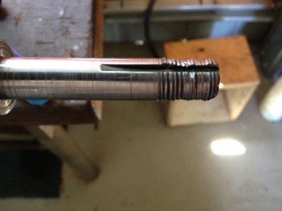
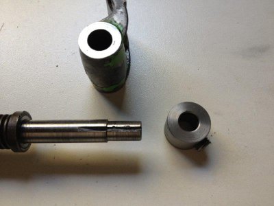
I managed to fix the lead screw. I had to cut the nuts with a hacksaw 90% of the way through and then just bust them off with a big screwdriver.
No additional damage was made to the shaft. I notice there was an unused keyway on the shaft which would make adding a hand wheel here much easier.
I might do that at some later stage.
I turned the stripped lead screw thread off and sized it to 7/16" in case I decide I really need another thread here later on.
I put the bracket in my 4 Jaw chuck and faced off both of the ends that were quite scuffed up from lack of oil and dirt getting in there I guess.
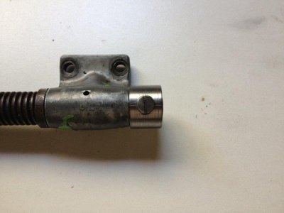
I left the step on the shaft about .005" longer than the width of the bracket so that it can't bind up again. A bit of play won't hurt as the force will all way be against the shoulder of the shaft when cutting from right to left (Right Hand Threads). I will rarely ever need to cut left hand threads. Also thinking about it the cross feed would not produce a force in either direction as it is driven by a straight key.
I know it is a honking big grub screw but I don't have a lot of taps at the moment. I don't have any grub screws either but I think the home made slotted grub screw will blend right in. (Don't tell anyone it is M10)
So one down and three or four to do
David
David
- - - Updated - - -
Hi Pierre,
Thanks for the info on the bevel gears. It think it is actually the 341-051 on my machine that has the missing tooth. I need to pull it apart again to confirm.
I think the Key is almost completely worn away in any case.
I'm sure I'll find a solution, I'm just trying to minimise the cash burn rate
David


- Joined
- Jan 28, 2011
- Messages
- 3,584
Turning down the end of the leadscrew is the best way to fix that problem. Welding new metal would work too, but lots more work for no real advantage in the end.
Yes you are correct that it is 341-051 that you have the broken tooth. The nice thing is that both mitre gears can be repaired/replaced with this bevel gear and some work of course.
Pierre
Yes you are correct that it is 341-051 that you have the broken tooth. The nice thing is that both mitre gears can be repaired/replaced with this bevel gear and some work of course.
Pierre
- Joined
- Nov 24, 2017
- Messages
- 64
Hi Guys,
I thought it was time I posted an update with the bits that I have fixed.
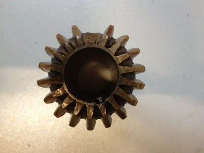
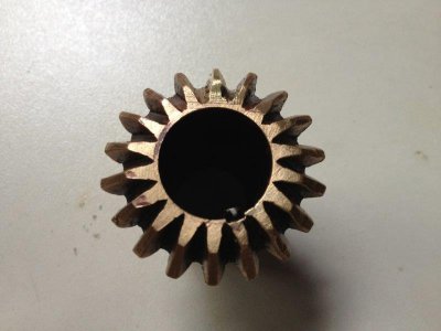
Next I addressed the cross feed gear with a missing tooth. I bought my self some braising rods and one of those Mapp gas torches. I heated up the gear to a bit more than a dull red and started to build up a new tooth. The torch I bought can only just melt the rod but I managed to build a nice blob where the tooth should be. I then dug out my trusty triangle file and started shaping the tooth.
I was surprised how hard the new tooth was, much harder that the bronze around it.
Check out the pictures I think it came out OK.
I reassembled everything and noted that it was still a bit crunchy when I spin the shaft. I went over all the teeth with a file and removed any bury bits. Also when the carriage was down the tail stock end the lead screw mysteriously tightened up. I discovered that if I loosened the bolts on the lead screw bracket the problem went away. I found if I shimmed out the bracket .020" this problem is also solved.
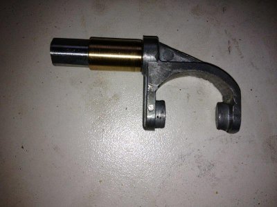
Next I turned to the reversing gears. I received the two parts I need, the selector gear from Terry above (Thanks!) and the selector arm I found on eBay. Once installed (more de-burring) every thing spins freely but the selector gear only just engages with either of the other two bevel gears. I noted that the shaft of the selector lever was quite loose in the hole of the gear casing. The front of the gear case was also slightly bent. After much thought and a big spanner I managed to straighten the case without snapping it. I then decided to drill out the hole in the case and with some more creative 4 jaw chucking turn down the diameter of the selector shaft. I then made a brass bearing with a light press fit onto the shaft and a nice fit in the new gear case hole. (See Attached)
It is all back together now and the engagement is much better but I still get it popping out of gear now and then. This may be because the bronze bevel gears are non original. The little spring loaded pin doesn't offer much resistance and there are multiple "V" groves cut into both lever positions none of which seem to be far enough away from the centre.
Stay tuned for more updates
David


