How to layout holes on an 8" diameter plate

Big Block,
One of my, to do, projects is adding a plate to the rotary table to be a clamping, sacrificial plate.
I would like to add a fence that is parallel to the milling machine table X feed when the rotary table is set to zero.
In order to accurately accomplish this the plate needs to be installed to the RT quickly and easily.
A smart fellow in our local group has his plate set up with close tolerance pins that slip into the RT's t slots.
Just throwing ideas around.

I like that idea and will incorporate it into my plans. thanks

I would also not make the plate round if it is currently square. The idea being that we do not know what our next project might be, so why cut anything off or drill anything until it needs to be for the current job.

The plate I have is 1/2" thick and it is already 8" round, that can't be changed.

On a fixture plate for a 4" RT, I would not make the threaded holes larger than 1/4"

I settled on 3/8 threaded holes because most of my clamping fixtures use 3/8's hardware and all of my T-nuts use 3/8 as well. Changing the hole size necessitated all new clamping hardware
 
Look at the first four videos in this list:

That first video was hard to watch. and hour of setup and 5 minutes of making a hole bigger. I'm pretty sure you wanted me to see his initial setup and the homemade clamps. I like that idea and may put it too use. My thinking is that after the top plate is made I'll make another thinner plate out of aluminum as a sacrificial plate.
 
For myself
I would just drill any holes that I need for the current project .
you can always drill more hole but plugging them and redrilling new holes can be very challenging
 
You could lay it out like a spider web wth diameters increasing every 1-1/2” and rays radiating from the centre. When the spacing of holes becomes too loose or too tight for your liking, add or delete a set of rays. Personally I think 3/8” holes on an 8” plate are way too big. I would go 5/16”, no more. It’s for clamping on a 4” RT, not holding up an engine block.

I do tend to agree with Bob though, regardless of where you put your holes there is an equal chance they will be in the wrong place. Been there several times.

-frank

View attachment 307273
This is sort of the idea with smaller and smaller rings that are offset to keep the spacing somewhere around 3/4" from any other bolt hole. I'll have a 3/8 hole and a 3/8 space in any direction I go on the plate.
 
R U sure it's a 47 inch circumference?
I think the calculation is off by a factor of 2. pi x 2 x r = pi x 7.5 = 23.56194. If I'm reading the OP correctly, sounds like the diameter was plugged into the formula instead of the radius. 2 x 23.56194 = 47.12389.

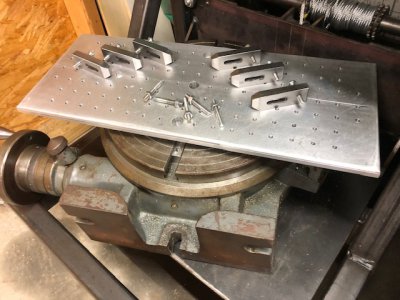
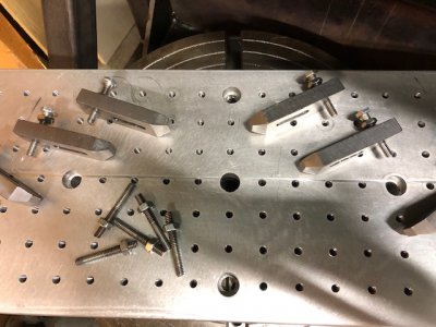
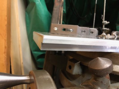
I have a 12" rotary table and made an indexing plate with toe clamps for it that works very well. Not nearly the same design, shape or size being discussed here, but all those are variable. It has a centering hole and four additional mounting holes for alignment on the RT. It is rectangular with a recess cut in the front and back edges so it can also be clamped in my vise, or mounted directly onto the mill table. The holes are all drilled and tapped to 1/4-20. I tried to design it to be as versatile as possible. Works pretty well, and it's hard to come up with a piece to machine that can't be attached to it somehow.

Regards,
Terry

IMG_0274.jpg

IMG_0275.jpg

IMG_0276.jpg
 
I think the calculation is off by a factor of 2. pi x 2 x r = pi x 7.5 = 23.56194. If I'm reading the OP correctly, sounds like the diameter was plugged into the formula instead of the radius. 2 x 23.56194 = 47.12389.

I have a 12" rotary table and made an indexing plate with toe clamps for it that works very well. Not nearly the same design, shape or size being discussed here, but all those are variable. It has a centering hole and four additional mounting holes for alignment on the RT. It is rectangular with a recess cut in the front and back edges so it can also be clamped in my vise, or mounted directly onto the mill table. The holes are all drilled and tapped to 1/4-20. I tried to design it to be as versatile as possible. Works pretty well, and it's hard to come up with a piece to machine that can't be attached to it somehow.

Regards,
Terry

View attachment 307340

View attachment 307341

View attachment 307342

You nailed my mistake. I plugged in the diameter instead of the radius. Oops! I do like that design and if the plate wasnt already round I would go with a square piece. It would be so much easier to lay out a hole pattern. I'm trying to do this with stuff I have on hand so I am ending up limiting myself.
 
You nailed my mistake. I plugged in the diameter instead of the radius. Oops! I do like that design and if the plate wasnt already round I would go with a square piece. It would be so much easier to lay out a hole pattern. I'm trying to do this with stuff I have on hand so I am ending up limiting myself.
Yes, I get that you're trying to use what you have on hand. (My indexing plate is its size and shape for precisely the same reason.)

I haven't thought this through completely, but I wonder if the simplest approach might be to carefully locate and mill your large center hole, then mount and center it on your rotary table. From there, you should be able to mill the additional holes wherever you want - including the ones to mount to the RT.. My kneejerk would be the outer set would be approximately equivalent to the numbers on a clock face - 12/1/2/3/etc. After you've done the outer set, you can fairly easily move to the adjacent set and decide if you want to line them up straight or stagger them (maybe 12:30/1:30/2:30/etc.). I think I would be inclined to chuck up a spotting bit first and just mark ALL the holes before cutting anything. That way, you can adjust if it doesn't look right. Totally different size/shape/pattern but that's essentially how I laid out my indexing plate.

Regards,
Terry
 
Quick PS: Obviously, you'll need to start somewhere. I can't visualize any way to mount an 8" piece of round stock on a 4" rotary table without first drilling a set of four holes that will line up with the t-slots. Maybe use a compass to lay out a circle (at 3" according to your original post?); then mill those holes first so you can at least mount it to the RT. Then proceed according to whatever pattern suits your objective.

I would suspect your FIRST measurement with a compass should be at @8" to make sure you're at or near centered. Then you're more likely to be where you want to be on the 3" circle.

Regards,
Terry
 
Back
Top