How To Hold This Part In Lathe?

Is the gasket sealing the water cooling, or is it sealing the combustion chamber? With a projected (proud) chamber, my understanding was that it was designed that way to keep from stressing the gaskets of the time, making the mechanical iron/steel parts do the bulk of the sealing.
 
I like the suggestion(s) to thread the bolt holes and using them for mounting to a faceplate.

Another way would be mount on a mill and use an automatic boring head.

I can't tell from the photos, but is the proud part a fire ring? If so, be careful how much you take off the gasket surface, you might want to check all your clearances once done.
 
Chris,
The projected area doesn't seal anything, maybe protects the head gasket from direct exposure to the ignited fuel.
The head gasket seals both the cylinder/compression, and the cooling water.

I'm planning to build a steel base plate to mount the head onto, since the bolt spacing is just a bit too big to fit on my lathe's face plate.
 
I wrote this before reading ALL the posts... didn't just delete because the comments at the bottom seemed to fit this situation very well.


Here's a complicated way to do it but a workable one. First open to boltholes up to the next thread diameter... meaning if the holes are slightly less than 5/16 drill them to that then thread for 3/8 if larger then do the same thing getting them to a common thread size. Once you have them threaded you are going to bolt the head to a faceplate through the back side of the plate. Getting it squared up may be the only real issue and you may have to make sleeves to run from the top of the head to the faceplate to get a good square mount for it. Once you have that done just face it off taking light cuts. Since the bolts for the head come down through the head, having the holes slightly oversize and threaded should have no effect on mounting the head back on the engine once you are done. There is an interesting thing about being a home shop hobby machinist. It's like a gunsmith once told me, you are typically faced with mounting or making a part that someone 100 years ago filed out of a piece of spring steel. There is no template, design drawing or print giving you direction for the order of machining operations to complete the project. You simply wing it.

Hobby machining is like that. And in truth it's why many folks steer clear of the hobby. There are a ton of yet to be discovered lathes and mills sitting in garages and barns that hardly got used because of projects like this head. The facing part is EASY. Mounting that on a faceplate or in a chuck is the hard part... It may take hours, facing it off should only take about 10 minutes.
 
I have an Atlas TH54/QC54 lathe, with basic tooling. (3 & 4 jaw chucks, face plate, steady rest, milling fixture etc) I have a part that I would like to face flat, but am not sure if I can do it with what I have available. The part is a cylinder head for an antique engine, about 6.5" dia, irregular shaped, with four thru-holes. I'd like to clean up the mounting/gasket surface as it was badly rusted. There is no way I can hold the part in a chuck, so my thought was to use a face plate, placing spacers to support the part on four bolts. The problem is that the bolt heads would be sitting right where I want to face the part. So is there another method to hold this? Something other than a bolt to hold the part?

Use studs instead of bolts. The studs will keep the head aligned and either a live center or live chuck ( rolling chuck) against the head .After you clean up as close as possible to the live center point, remove the head and clean the area where the point touched by hand.Even if the studs are proud of the head,face them as you do the head itself.

mike
 
I stand on my suggestion to make a mating part to lap in but I add epoxy.

Get some exhaust or muffler repair epoxy and buff head clean with wore wheel then clean it again.

Scrub with acetone then mix batch of epoxy and thin with acetone and pour it in the mating area and scrub it into all pits with brush then let it cure for a week.

Cut out a sand paper ring same as gasket of wet dry and with the lapping plate hold all in running water and lap off the epoxy and you will have a perfectly flat Un - pitted surface.


Sent from my SAMSUNG-SGH-I337Z using Tapatalk
 
Just thought I'd follow up on this post to show how this project played out.. Thanks to all for the tips & suggestions!!
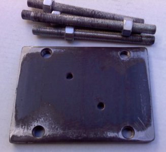
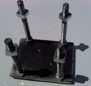
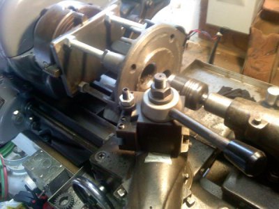
I bought a rectangular piece of steel plate large enough to take the (tapped) hole pattern, and to allow the chuck jaws to clear the post on the part. Also four threaded studs with nuts. (Surprising how UN-flat a piece of bar stock can be.)
0806061310.jpg .
0806061321.jpg.
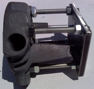
The two tapped holes in the center are where 2 bolts will pull the part against the stud spacers.


0806061337.jpg.
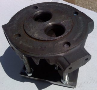
0806061336.jpg.

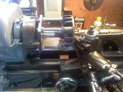
Next was to clamp the assembly in the 4-jaw. And with much trial & error, got it dialed in to what seemed to be centered and with the face running basically flat and true. (it was hard to tell as it was eroded away so badly) The tail-stock was used to support the part & keep it seated against the chuck.

0812061551.jpg
0812061553.jpg

I carefully started the lathe & ran it at a slow speed, and using cross feed. I was surprised at how easily the tool took to the cast iron. (ok this was my first time working with cast iron.. and first chance to use the power cross feed.) I thought maybe the holes would cause problems, but no problem. Several light passes later and the part looked great, even better than I thought it would do! I didn't get all the pitting out, but it did clean up in the areas where the gasket seats and does its sealing.
This job turned out so well that I quick disassembled my antique water pump (which was leaking at the end gasket) and turned the face on its end gland too! It worked out great also, no more leaking!
So I'm happy with the results. Thanks to all for the suggestions that helped me complete this job!!
Wes
 
Nice work. " I love it when a plan comes together."
 
Back
Top