Per Ulma Doctor,
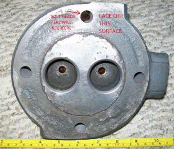
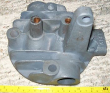
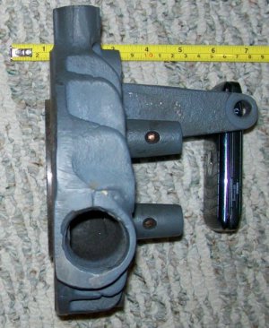
So something like: Starting out with an aluminum round or square plate (something like 1/2" by 7 - 8") to use as a mount in the lathe chuck, mill or saw out the section on the mount for the head mounting bracket on the head. Turn 4 posts that will snugly into the head mounting holes so they have a shoulder on both sides (this will provide better stability and set a fixed distance between the head and plate) and fasten the other ends into the aluminum plate (thread the standoff or bolt through). The length of the four posts between the shoulders need to be slightly higher than the valve guides and allow enough space behind the mounting plate for the head mounting bracket, so about 2.5" between the mounting plate and head bolt holes. Drill two holes in the mounting plate to align with the valve guide holes, use washers with bolts extending through the valve guide and into the aluminum plate. These will tension the head to pull it down against the 4 posts. The 4 posts just act to stabilize the head. I would make sure on the bolts there is no thread up against the valve guide, you do not want the thread to damage the guide if there is any movement.
It looks like the two valve guides and 4 head mounting holes are all symmetrical around the center of the head, so you could just pull off the measurements and build a jig to hold the head. You may want to use a 4J independent chuck if you need to center the milling area. If using a square plate in a 4J, may want to use some spacers between the chuck and the mounting plate so it stays parallel when turning. Low speed, sharp cutter, multiple light passes. Sometimes I mock things up with wood to check clearances.
Other option would be to use a mount in a rotary table on a mill.


