Hemingway Knurling Tool drawing help

The companies doing these kits and models seem to take that to the extreme lol. I usually redraw these drawings into something usable at the machine, it helps with figuring out what their intent was, and sometimes you find mistakes before you start cutting metal.
Yep, and I reckon your process is a good habit anyway.

As you say, it makes sure you answer any questions you might have and prevents mistakes, either due to a drawing that is less than generous with information, a drawing that genuinely has missing information, or even contains genuine mistakes.

It also can help to reduce the chances of our own misreadings or plain old fekwittery (the latter being something I personally, am well acquainted with! :grin:) getting through.
 
Clearance for the knurl wheel . Can't see why it would be important and sure can't figure out what he was dimensioning .
 
Clearance for the knurl wheel . Can't see why it would be important and sure can't figure out what he was dimensioning .
My bad - I mean the hole. There's a little retaining screw that goes there
 
My bad - I mean the hole. There's a little retaining screw that goes there
I can't figure out what that small tapped hole would do . It isn't capturing the shaft . Usually a hole would be drilled and tapped in the very end of the holder keeping the shaft from spinning . The other option was to use shoulder bolts and nuts . This drawing is not very clear . :grin:
 
The hole holds down an annoying small part that fits into a groove on the pin that the cutter rides on. Googling around it looks like most have taken a different approach
 
The hole holds down an annoying small part that fits into a groove on the pin that the cutter rides on. Googling around it looks like most have taken a different approach
What does the drawing of that other 'annoying' part show?

Is the 'annoying' part that fits into the wheel shaft, a substitute for a circlip or e-clip?

If it's just a retaining screw for such a part then, in this case, it probably doesn't matter. You'd just pick an appropriately sized screw that you had available and drill and tap for that sized threaded hole as needed.

That said, it probably would be better to be dimensioned on the drawing (these drawings were made mostly by model engineers who would have certain assumptions about those reading the drawings and their pre-existing knowledge; assumptions that may no longer be reliable), so it might be worth dropping Hemingway an email asking about the omission.
 
The hole holds down an annoying small part that fits into a groove on the pin that the cutter rides on. Googling around it looks like most have taken a different approach
Given an understanding of the function, I think the only thing that matters is that the hole be 11/32" from the spindle. i.e. the angle of that stupidly shown dimension is irrelevant.

GsT
 
Given an understanding of the function, I think the only thing that matters is that the hole be 11/32" from the spindle. i.e. the angle of that stupidly shown dimension is irrelevant.

GsT
True. Good point.
 
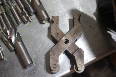
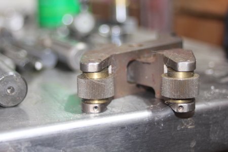
I made some small and large knurlers based off the Eagle Rocks back when we had down time in the shop . I used dowel pins and also had brass bushings between the wheels and tool . I tried to get a close up of the set screw to capture the shaft . Not sure if it will show up on this pic . Edit . You can see it ! :encourage:
 

Attachments

  • IMG_2268.JPG
    IMG_2268.JPG
    413.1 KB · Views: 24
  • IMG_2269.JPG
    IMG_2269.JPG
    310.1 KB · Views: 24
Back
Top