Has anyone installed Clough42's electronic leadscrew on a PM machine?

My encoder doesn't have a keyway, it has a flat on the 6 mm shaft. I bought an aluminum pulley, 40 tooth, 15 mm wide with 6 mm bore. I turned the hub off of it, then drilled and tapped through the pulley teeth for a set screw.

Once you make for spacer for the shaft and have it installed in the pulley you should be able to do the same.
As you mention, the 6mm encoder shaft is designed to work with a set screw, which works for that end of the connection. The other end of it is the pulley. I solved the problem by machining a 12mm shaft down to 10mm for the pulley and the threading a hole into the shaft end. Now I can use a M5 screw and washer to bear on one side of the pulley and the other side bears on the shaft step. The pulley is squeezed between the two, so it's held nicely in place.

Of course, as I note in the post above, it probably will end up being a pulley that doesn't work with the spindle "gear". So I may be restarting from scratch again.
 
Cog belts and gears don't have meshing teeth to my knowledge. You need to convert from one to the other.

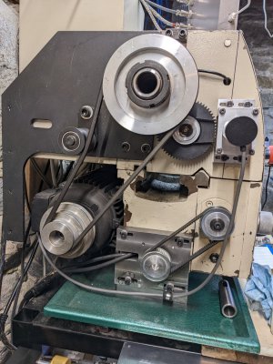
On my lathe I have a separate shaft with a gear (think it was 60T) that engages the spindle gear. In the picture below it is the black plastic gear. On that shaft, I mounted a cog belt pulley. The cog belt pulley shares the same key as the gear. That way they turn together. Then I connected a cog belt to my encoder. Not the only way to do it, but a way that worked for me.

This is a picture of what I did. Had to recess machine the cog pulley a little, since the shaft wasn't quite long enough. Since the main pulley is aluminum, it was fairly easy to do.

I didn't use a full gear connection, because I found I couldn't get both the ratios that I wanted, nor could I get the gears to mesh, with a simple design. So I went to this approach, which was easier to get the desired ratios, and had more degrees of freedom for placement of the encoder bracket. Hope this helps some. No, it isn't your lathe, but maybe you can do something similar.

The black gear engages the spindle gear (not visible). The common key turns the cogwheel at the same RPM. The cogwheel turns the cogged belt, which turns a small cogged pulley on the encoder shaft.
PXL_20221206_145029684.jpg
 
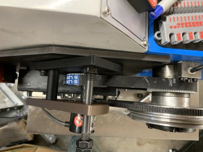
I went down the path of trying to use the spindle gear directly. Bought a T5 belt and T5 40 tooth pulley. Got everything in place this morning and noticed the belt occasionally did a little "hump" movement. And then I realized, the spindle gear must not be T5. It's close, but not close enough. A picture makes this very clear.

View attachment 471681

This is on a PM-1130v. Does anyone know what tooth pattern is used on the spindle gear for my lathe? It definitely doesn't mesh properly with a T5 belt. I'm guessing that it may not mesh with any available timing belt :(
That is a module 1.5 spur gear, not a timing belt pulley. M1.5 is like as 4.71mm pitch (multiply module by pi to get pitch) so it almost but not quite fits.

WobblyHand has excellent advice. The other option is to buy another 40 tooth T5 timing belt pulley and bore it out so it fits your spindle.
 
That is a module 1.5 spur gear, not a timing belt pulley. M1.5 is like as 4.71mm pitch (multiply module by pi to get pitch) so it almost but not quite fits.

WobblyHand has excellent advice. The other option is to buy another 40 tooth T5 timing belt pulley and bore it out so it fits your spindle.
Yep. Looks like I went down the wrong path. :) It seemed so much cleaner to avoid an intermediate shaft with all the mounting hardware and lubrication stuff.

The spur gear on the spindle looks difficult to replace. It has a large keyway which it shares with the pulley for the motor drive. And the pulley bears against it, pushed with a huge threaded nut. If it wasn't in the middle of the drive train for the spindle, I might be able to 3d print a part that would work. But, I doubt that's a good long term solution.

I just ordered an aluminum 40 tooth T5 pulley. It's going to be pretty darn difficult to hold for turning. And I'll get another chance to broach a keyway.
I didn't want to deal with my spindle gear either. Actually I tried, and nothing moved, so decided to use the intermediate shaft which was already there. It was the path of least resistance, for my abilities at the time. I could have made a new intermediate shaft, one that was longer, but ended up just recessing the end of the cogwheel so an e-clip could hold the pulley to the shaft. It has been working fine.

I had to broach the keyway on a few pulleys. Fortunately, had an arbor press. Ended up buying an import broaching set, which worked out ok. I've broached by hand on the lathe (in steel) before and decided to splurge on the broaching set. Made the job a bit easier.
 
I got a new pully/gear for the spindle from another person here. Made from aluminum and fit perfectly. It was an easy swap.

I bet if one was 3D printed at very high (or 100%) fill it would be just fine. The ‘nut’ holding it all together was not that tight at all when I took it apart.

Picture was with belt etc not fully aligned yet.
 

Attachments

  • IMG_7842.jpeg
    IMG_7842.jpeg
    323.4 KB · Views: 73
A broach set sounds nice. But cutting a broach on something close to a 2" ID seems fairly scary. And pretty expensive.

Al least it's aluminum. I should be able to do most of the keyway material removal on my PrintNC mill with an 1/8" bit. It will leave round corners and I can square them up with a hand file if nothing else.
 
I went down the path of trying to use the spindle gear directly. Bought a T5 belt and T5 40 tooth pulley. Got everything in place this morning and noticed the belt occasionally did a little "hump" movement. And then I realized, the spindle gear must not be T5. It's close, but not close enough. A picture makes this very clear.
I had initially tried the same thing and had the same result as you. Knowing it is a module 1.5 gear I decided to get a 60 tooth plastic gear from Grizzly for a G0602 and then run 60 to 40 GT2 belt for my encoder. I figured the plastic gear with the little load that's on it would need minimal lubrication and probably run quieter. The gear from grizzly does fit directly to the PM gear parts. I think the ultimate thing to do would be to put a belt pulley on the spindle. The way it is now I can switch back to the geartrain if the need arose. I like your install of the servo motor. On my 1130v fitting where you did was a no go, wasnt even close to fitting between the motor and bed. My second plan was the 5:1 worm gearbox which works but seems to add enough extra drag that the servo has a hard time turning the gearbox. I will likely switch to your servo mounting when I have time to space the motor farther away from the bed
 
I got a new pully/gear for the spindle from another person here. Made from aluminum and fit perfectly. It was an easy swap.

I bet if one was 3D printed at very high (or 100%) fill it would be just fine. The ‘nut’ holding it all together was not that tight at all when I took it apart.

Picture was with belt etc not fully aligned yet.
Lot's of ways to do it. A 3d cog would work fine, driving an encoder is not a high torque application.
 
I got a new pully/gear for the spindle from another person here. Made from aluminum and fit perfectly. It was an easy swap.

I bet if one was 3D printed at very high (or 100%) fill it would be just fine. The ‘nut’ holding it all together was not that tight at all when I took it apart.

Picture was with belt etc not fully aligned yet.
If you can find the records of the source for your replacement gear, please let me know!
 
Back
Top