-
Welcome back Guest! Did you know you can mentor other members here at H-M? If not, please check out our Relaunch of Hobby Machinist Mentoring Program!
You are using an out of date browser. It may not display this or other websites correctly.
You should upgrade or use an alternative browser.
You should upgrade or use an alternative browser.
Harbor-Freight 3 in 1 Motors?
- Thread starter Richie B.
- Start date
- Joined
- Nov 2, 2014
- Messages
- 21
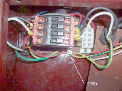
OK, here's what I did: Hooked up my multimeter in continuity test mode and checked the Green [110v input]wire - no ground. (That was pretty obvious). The Green/Yellow wire with the "E" label - got ground to both motor frames, the enclosure, the machine frame, ways, gears, etc. The two unmarked Green/Yellow wires - no ground.
So, I knew I had to attach the input Green wire to the enclosure, and the Green/Yellow "E" wire as well. Taking Robert at his word, I also attached the other two Green/Yellow wires to the enclosure stud as well.
Plugged it in, started it up...Both motors turn over, forward and reverse, indicator light comes on, shutoff works.
I'm guessing it's 'right'...
Thank you all again for your help!

Your assumption is correct, all four wires should be bolted to the frame of the machine. While everything "works" without the ground wires being attached, it does not provide a safe return path to ground in the event of an electrical short within the equipment.Sorry; I should have been clearer - I put the tape on the wire ends. They all have a small ring connector on the end. Pic below - View attachment 90732 When I took the metal shield off, the wire rings were not connected to anything, but a small nut fell out. There is one screw for the 'panel' that is longer than the other three. I taped up the wire ends to see if the motors would run without them. They do - both forward & reverse. I can only guess that they are grounds for each individual motor, and that when I unscrewed the 'panel' to replace the plastic grommet nut for the input 110v wires, a small metal nut fell off and the wires came loose. I have the small metal nut. I'm going to test continuity between each motor body and the end of any of the wires and see if they are 'grounds'. That is about the limit of my diagnostic skills in electric circuits. Everything seems to work without the wires being connected to anything.
- Joined
- Nov 2, 2014
- Messages
- 21
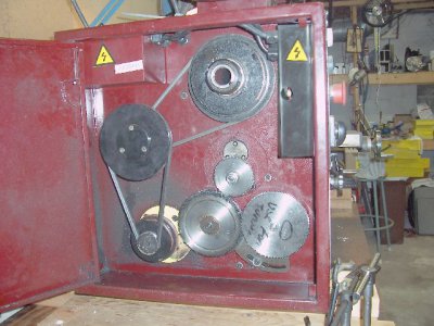
BTW: If you're wondering why an 'electrically challenged' dummy like me is poking around in electrical enclosures, it's because on the 44142 3in1, the gears for changing the feed are in the enclosure. They have to be manually unbolted, removed, and exchanged. There is some oil seepage into the 'sump' of the enclosure which I periodically wipe out.
Last time I was threading a shaft, I noticed chips in the sump. Looking around for entrance areas was when I saw the input wire grommet had worked loose and was letting chips in. It's about a one inch hole, and the input wires were resting on the sharp edge of the steel enclosure.
So that's why I was poking around in electrical boxes.


Last edited:
- Joined
- Feb 8, 2014
- Messages
- 11,176
As far as I know, ground is on the schematic as P.E.
Yup, that is the normal ground designation on European and Asian schematics. P.E. = Physical Earth
- Joined
- Dec 25, 2011
- Messages
- 10,552
Not actually always. In electronic equipment, it may be used for example on the center-tap of the 6.3 VAC filament winding of a filament or power transformer. And may or may not be grounded, depending. But in electrical (as opposed to electronic) equipment, it would be a fairly safe assumption that it meant safety ground on any equipment not made in North America, where the standard is Green with no stripe.
Robert D.
Robert D.
Green/yellow is always ground. http://en.wikipedia.org/wiki/Electrical_wiring#Colour_code
- Joined
- Dec 8, 2013
- Messages
- 2,651
Not actually always. In electronic equipment, it may be used for example on the center-tap of the 6.3 VAC filament winding of a filament or power transformer. And may or may not be grounded, depending. But in electrical (as opposed to electronic) equipment, it would be a fairly safe assumption that it meant safety ground on any equipment not made in North America, where the standard is Green with no stripe.
Robert D.
In electronic equipment all bets are off as to color codes.
Green-no-stripe is by far the most common for safety ground in the USA but green-yellow is allowed by the code, as is bare.
- Joined
- Mar 3, 2013
- Messages
- 1,448
Source for motor run and start caps:
Surplus Center:
http://www.surpluscenter.com/Electrical/Capacitors/
McMaster Carr:
http://www.mcmaster.com/#motor-capacitors/=v7y04p
Grainger:
http://www.grainger.com/category/motors-motor-supplies-capacitors/ecatalog/N-9yp/Ntt-motor+capacitors?nls=0&sst=subset&ts_optout=true
Surplus Center:
http://www.surpluscenter.com/Electrical/Capacitors/
McMaster Carr:
http://www.mcmaster.com/#motor-capacitors/=v7y04p
Grainger:
http://www.grainger.com/category/motors-motor-supplies-capacitors/ecatalog/N-9yp/Ntt-motor+capacitors?nls=0&sst=subset&ts_optout=true
- Joined
- Nov 2, 2014
- Messages
- 21
Source for motor run and start caps:
Surplus Center:
http://www.surpluscenter.com/Electrical/Capacitors/
McMaster Carr:
http://www.mcmaster.com/#motor-capacitors/=v7y04p
Grainger:
http://www.grainger.com/category/mo...or+capacitors?nls=0&sst=subset&ts_optout=true
Eurton has exactly what I want -
http://www.hobby-machinist.com/show...-3-in-1-Motors?p=258610&viewfull=1#post258610
Two sets of caps are on the way!
- Joined
- Oct 27, 2014
- Messages
- 272
For future reference to anyone else, these site occasionally has some fun stuff:
http://www.mpja.com/
http://www.goldmine-elec-products.com/
(No, I didn't see any caps!)
http://www.mpja.com/
http://www.goldmine-elec-products.com/
(No, I didn't see any caps!)
