Harbor-Freight 3 in 1 Motors?

I guess my next question is where is a good place to order a pair of 300uF/250v Start caps and 35uF/250v Run caps??? Amazon does not list anyone selling the 35uF caps, and the Mouser caps list minimum quantity:32...

I'm not into electronic parts suppliers; the only catalog I have here is from Grainger, and they don't list the 35uF/250v Run caps...

I'm also in an industrial-challenged area; if there's an electronics supply facility around here, they're well hidden...

Mouser use to cater to hobbyist and their small quantity purchases. Its been a decade since I did business with them, that is sad to see. You might try calling them or just check with Digi-Key. Lots of surplus electronics places would have them also. Google search the values you need. Another option for anything industrial is McMaster Carr, fast shipping, low prices and a great online catalog.

Happy Holidays
michael
 
I think I found a dealer selling both caps -

http://store.eurtonelectric.com/capacitors.aspx


"START" CAPACITORS 125-300 VAC

http://store.eurtonelectric.com/capacitorcd60-850uf300vac-1-1-1-1-1-1.aspx

Capacitors CD60-8300 300 uf (MFD), 300VAC

Price: $20.00
Item Number: CD60-8300


"RUN" CAPACITOR 250-450VAC

http://store.eurtonelectric.com/capacitorcbb60-a21212uf250vac-1-1-1-1-1-1-1-1.aspx

Capacitor CBB60-A235 35uf 250VAC

Price: $11.20
Item Number: CBB60-A235


It'll be a band-aid until I can get new 'yankee' motors and sheaves, but it should get me through the Winter...
 
Those links look good (be wary of those non-representative stock photos lol). Assuming the dimensions match up, I think those might keep your old Chinese motors running for quite a while.

Also, if you're interested in seeing if the motor is pulling 500W or is outputting 500W, you might want to get one of the Kill-A-Watt watt meters that go inline with the 120V plug. They're about $20 on Amazon.
 
I'll add that electronic outlets like Digi-Key and Mouser are not the sort of place where you want to look for AC motor or electrical distribution system components. They may have a few bits, but their business is electronic, not electrical. You need an industrial electrical supply house.

Also, I have just discovered that the voltage ratings marked on Start and Run capacitors don't all use the same standards. Some are as I said earlier, RMS. If the rating says 125 VAC or 250 VAC, it is probably RMS. If it says 370 V or 600 V it is peak for use on 208/240 VAC or 440/480 VAC systems and motors. I haven't found an example for 110 or 120 VAC systems but it is probably something close to 200 V. Confusing, I know.

I have also found some more disinformation typical of the Internet. One place that I just looked at says that the oil found in most run capacitors is a coolant. While it does contribute to dissapating the heat generated during the motor run time, its primary purpose is as part of the dielectric.

Robert D.
 
Thank You all for your replies! I think I have a rudimentary understanding of motor capacitors now, enough to recognize which one has burnt up and what I need to order to replace it! :)

The next one that goes, I'll pull it out and take it to my local motor shop and find out what size/model of 'yankee' electric motor can be made to fit.
 
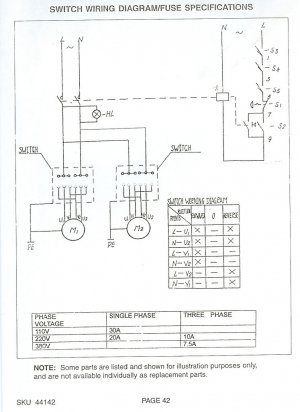
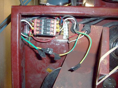
I did some normal cleanup/maintenance on the 3in1 today, specifically the electrical enclosure...I mopped up oil that had seeped in, and while wiping down the outside of the box I noticed that the 110v input wire hard plastic grommet was missing its nut...It had come loose and fallen down inside a steel box in the enclosure... I undid the screws and opened the box, and the first thing I saw was four loose wires...and a tiny nut fell out... I could not find anything to put the nut on, or any other loose wires...I taped the loose wires up and shut everything up and tried the machine...Both motors worked, F & R, 'On' light illuminated... I have no idea what these four wires are for...they're Green with a Yellow stripe...I thought maybe there was a ground wire somewhere that came loose, but I don't see any Black [ground] wires anywhere... Here's the wiring diagram from the manual...

wiring.jpg

I don't see any 'Ground' symbols... Is it possible the Chinese use Green w/Yellow stripe as [motor] ground??? One of the screws holding the circuit board onto the enclosure is longer than the others... (Pic of box below)

wiring2.jpg

Edit: Input wires [110v] are Black, White, and solid Green...

wiring.jpg wiring2.jpg
 
Last edited:
It's likely the four wires are for each of the motor's circuits. If you look at the diagram you will see the 120VAC input line and the switches. From the switches, the line voltage makes contact with some of the V and U terminals. There are probably some jumpers in there as well based on the wiring diagram (above M1 and M2) to make the motors run in reverse. I tried to find a copy of a diagram I have in my notes that is a great reference, but it looks like I'll have to take a photo of it and upload it later.

I don't like how there are two wires that appear to have been cut and taped off with electrical tape. Can you see if they go anywhere?
 
Richie,

First, in the US and Europe, there are two totally different systems or approaches to standard colors for wiring, electronic and electrical. In electronic equipment, which usually includes vehicular and aircraft, black is typically ground or chassis or common or B- (if B- is floating as it was in some early radios like the BC-654). Green is commonly either filament or grid, more often the former in transformer operated equipment. Red and Blue are B+ and Plate. Etc. In electrical at least in the USA, black is the hot wire for 120 VAC systems. It should never be used for a ground wire. White is neutral. Green is ground. Red is the other 120 line color in 120/240 systems. I have seen green with a yellow tracer used for the ground wire in some European made power cords, instead of solid green. Don't know why.

Anyway, it would appear that the Chinese did not run ground wires around internal to the machine, although the wires are there. There really wouldn't be any need to as the whole machine would be bolted together. If one of the motors was mounted on rubber cushions or on swinging mounts or bolted to the bench separately from the machine, as is common with a lot of older US built equipment, then you would need to run the copper ground wires around. It looks to me like they used standard cordage and left the unused wires dangling. Not neat and workman like but not dangerous, either. Just confusing. I would first find where the other ends of all of the Gn/Y wires go but probably you could just tie all of them together and to a ground stud.

You are correct about the lack of a ground symbol on the inputs in the schematic. The schematic certainly wouldn't pass UL.

Robert D.
 
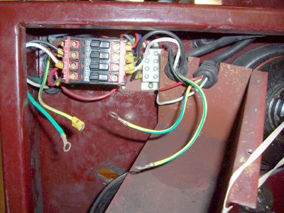
Sorry; I should have been clearer - I put the tape on the wire ends. They all have a small ring connector on the end. Pic below -

View attachment 90732

When I took the metal shield off, the wire rings were not connected to anything, but a small nut fell out. There is one screw for the 'panel' that is longer than the other three. I taped up the wire ends to see if the motors would run without them. They do - both forward & reverse.

I can only guess that they are grounds for each individual motor, and that when I unscrewed the 'panel' to replace the plastic grommet nut for the input 110v wires, a small metal nut fell off and the wires came loose. I have the small metal nut.

I'm going to test continuity between each motor body and the end of any of the wires and see if they are 'grounds'. That is about the limit of my diagnostic skills in electric circuits.

Everything seems to work without the wires being connected to anything.

wiring3.jpg
 
Last edited:
Back
Top