-
Welcome back Guest! Did you know you can mentor other members here at H-M? If not, please check out our Relaunch of Hobby Machinist Mentoring Program!
You are using an out of date browser. It may not display this or other websites correctly.
You should upgrade or use an alternative browser.
You should upgrade or use an alternative browser.
FT-1 and DRO Install
- Thread starter D. Kent
- Start date
Reviving this thread after noting my manual Y dial indicator is sticking, and is in dire need of replacement; I've figured it's time to upgrade to DROs- I have too many Mill needs to start moving on this "want" that has become a need.
I was originally thinking cheapo glass scales, 2 axis, browsed through Amazon, after some re-searching around I thought I had settled on DRO PROs, but after a rudely bizarre phone call and exchange of emails today I'm back to shopping for a DRO kit. The Aikron kits are appear best priced for magnetic scales. Looking at the scale combinations at MachineToolProducts I'm thinking that even though a 36" scale is a lot more length than the available travel on my 42" table and the product note the scale is 4" longer than travel, SHOULD work.
Anyone using Aikron box and if so, likes, dislikes?
The three axis kit (16X36X16) is $100 more compared to the two axis (16X36). It seems worthwile to get the extra capability even though my most basic needs are 2 axis. Hmmm.
Just purchased, more to come.
Last edited:
- Joined
- Dec 21, 2018
- Messages
- 2,020
No Idea about Aikron but I like having X, Y & Z on the knee.
Very often the knee needs to be moved to change tooling lengths (drill to boring head or to reamer & nice to come back to the original reference location. I usually use INC to store my reference location as 0,0,0 and use ABS as my working scales. I've got Easson DROs on both the mill & lathe, they've been good.
Very often the knee needs to be moved to change tooling lengths (drill to boring head or to reamer & nice to come back to the original reference location. I usually use INC to store my reference location as 0,0,0 and use ABS as my working scales. I've got Easson DROs on both the mill & lathe, they've been good.
- Joined
- May 3, 2020
- Messages
- 316
Do something simple.
I tried to install my DRO inside the machine. Something recommended by Renzetti but I'm not sure it's worth the trouble on an RF-45 class machine. Everything is tucked neatly away but it took me a lot of time.
Quill

Y

Z. Ran out of patience.

X. This one was a doozie


I tried to install my DRO inside the machine. Something recommended by Renzetti but I'm not sure it's worth the trouble on an RF-45 class machine. Everything is tucked neatly away but it took me a lot of time.
Quill
Y
Z. Ran out of patience.
X. This one was a doozie
Update: The Aikron 3 Axis kit arrived in two boxes via DHL, signature required. The first was the readout itself and the second were the scales, sensors, and 3 angle brackets. So far, the good: everything arrived in good condition, as quoted, within 5-7 business days. The cons: what I expected at this price point, the documentation and hardware is sorely lacking, but it isn't rocket science either.
One item that I've wondered about are the mounting brackets and their use. It's appearing like I'll need to fabricate a mounting block for the sensor for the X axis to work with the supplied bracket. At the back of the table I run the risk of crashing into sensor's bracket if Max out my Y travel, so, the X scale mountined on the rear of the table isn't perfect, but is better than placing in front and rendering the front T-bolt slots useless. Would love to mount in the carriage, but I don't havae that sort of patience")
The Y is a different story and there are a couple of different routes I can take. The existing scales are manual, with a roller wheel that rides along the front of the table for X and for Y, along a machined bar mounted on the right hand side of the knee, under the carriage. The indicators themselves are mounted on adjustment blocks of sorts that bolt to a what appears a 'stock' casting to fit the mill's carriage. Unfortunately, the Y travel bar is offset out toward the opeartor from the knee to account for the casting location, at the front of the table, below the carriage. I should take a photo.
I have a couple of possible options, maybe more:
1) mount the new scale to the Y tavel bar, mounted as is on the knee, make a custom block to fit the stock casting and place the sensor where the old roller wheel used to be. This will require additional clearance to accomodate the scale, resulting in a needed "notching" of the casting.
2) An alternative would be to remove the Y travel bar and indicator casting all together, mount the scale directly to the knee. This entails drilling new holes on the bottom of the carrieage for the sensor's bracket, I'll still need a sensor mounting block, using the supplied bracket, and drilling holes into the knee. I like this location better as it directly under the table, instead of in front of it.
3) A variation of above except drill a couple new counter bored mounting holes on the bar to reposition backward onto the knee, rather than drilling holes and mounting the sensor under the carriage The knee casting is rather clean in that area.
I am beginning to wonder about my approach on the knee for mounting Z. There's not a lot of room to mount the scale on the knee because of the knee locks on the left and lube port on the right. Maybe mount the scale on the mill body with the sensor on a backet that is bolted to the knee?
I'm starting to keep a list of details together....For example, you'll need a M6 bottom tap and 13/64" drill to mount the DRO display mounting arm to your mill. Something tells me a formal drawing for the spacer blocks will be appreciated by others, using the Aikron brackets / kits.
One item that I've wondered about are the mounting brackets and their use. It's appearing like I'll need to fabricate a mounting block for the sensor for the X axis to work with the supplied bracket. At the back of the table I run the risk of crashing into sensor's bracket if Max out my Y travel, so, the X scale mountined on the rear of the table isn't perfect, but is better than placing in front and rendering the front T-bolt slots useless. Would love to mount in the carriage, but I don't havae that sort of patience
The Y is a different story and there are a couple of different routes I can take. The existing scales are manual, with a roller wheel that rides along the front of the table for X and for Y, along a machined bar mounted on the right hand side of the knee, under the carriage. The indicators themselves are mounted on adjustment blocks of sorts that bolt to a what appears a 'stock' casting to fit the mill's carriage. Unfortunately, the Y travel bar is offset out toward the opeartor from the knee to account for the casting location, at the front of the table, below the carriage. I should take a photo.
I have a couple of possible options, maybe more:
1) mount the new scale to the Y tavel bar, mounted as is on the knee, make a custom block to fit the stock casting and place the sensor where the old roller wheel used to be. This will require additional clearance to accomodate the scale, resulting in a needed "notching" of the casting.
2) An alternative would be to remove the Y travel bar and indicator casting all together, mount the scale directly to the knee. This entails drilling new holes on the bottom of the carrieage for the sensor's bracket, I'll still need a sensor mounting block, using the supplied bracket, and drilling holes into the knee. I like this location better as it directly under the table, instead of in front of it.
3) A variation of above except drill a couple new counter bored mounting holes on the bar to reposition backward onto the knee, rather than drilling holes and mounting the sensor under the carriage The knee casting is rather clean in that area.
I am beginning to wonder about my approach on the knee for mounting Z. There's not a lot of room to mount the scale on the knee because of the knee locks on the left and lube port on the right. Maybe mount the scale on the mill body with the sensor on a backet that is bolted to the knee?
I'm starting to keep a list of details together....For example, you'll need a M6 bottom tap and 13/64" drill to mount the DRO display mounting arm to your mill. Something tells me a formal drawing for the spacer blocks will be appreciated by others, using the Aikron brackets / kits.
Last edited:
- Joined
- Dec 21, 2018
- Messages
- 2,020
The generic brackets that come with DROs rarely fit all (any of) the mills. Luckily you have a mill to make the needed ones. I also opt to mount the X scale on the back side of the table. I wanted to retain the limit switching for the X feed. The loss of a bit of Y travel isn't a big deal since I can move the ram in & out as needed. Having limit switches for the power feed on the knee is also a good idea. I put a feed on the knee after getting really tired of cranking it up & down when needed for tooling changes (drill to reamer or boring head etc.) I'll admit to being lazy but each turn of the knee crank doesn't move the table much.
- Joined
- Oct 14, 2013
- Messages
- 1,216
That is some really impressive work!
Sent from my SM-S911U using Tapatalk
Sent from my SM-S911U using Tapatalk
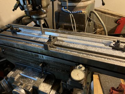
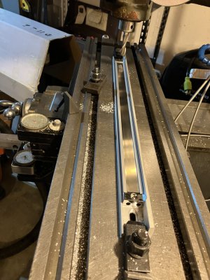
Short update: I happen to have an Acu-rite / Heidenhain mounting kit for the Y axis and decided to modify the mounting "spar" it to fit the Aikron scale that is slightly taller by ~0.071" I've also been modeling the X axis in SolidWorks to ensure the sensor mounting block is the correct dimensions. The benefit of using the spar is that is acts as a decent chip guard.
Attachments
- Joined
- Apr 23, 2018
- Messages
- 6,739
There! I fixed it for you. Lagun owners watch out for one another like that.The benefit of using the spar is that is acts as a decent chipguardstorage shelf.
The Trav-a-Dials still work? Never used one, but they seem cool. I've been thinking of attaching one to the long traverse on my lathe because I don't really want a DRO.
The manual indicators still work, but don't tolerate cutting fluid much. The Y axis indicator tends to stick.
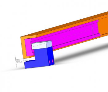
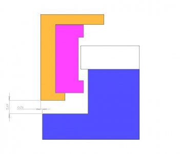
I located another spar for the X-axis and spent a few minutes modeling the spar-scale-sensor in an old version of SW to ensure the mounting block's design will work, theoretically.
If anyone is curious: the Aikron "AOM" scales use a 5MM button head screw to mount and the Acu-Rite Spars use 1/4-20 to mount to the knee and table. The Aikron sensor uses 3.0x0.5 cap bolts.
I'm looking forward to the sensor mounting block (blue) being the last part I rely on the mechanical indicators (at least for the table).