
-
Welcome back Guest! Did you know you can mentor other members here at H-M? If not, please check out our Relaunch of Hobby Machinist Mentoring Program!
You are using an out of date browser. It may not display this or other websites correctly.
You should upgrade or use an alternative browser.
You should upgrade or use an alternative browser.
FT-1 and DRO Install
- Thread starter D. Kent
- Start date


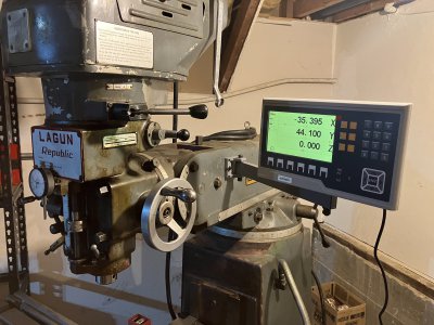
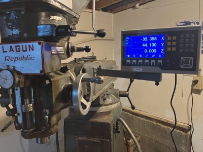
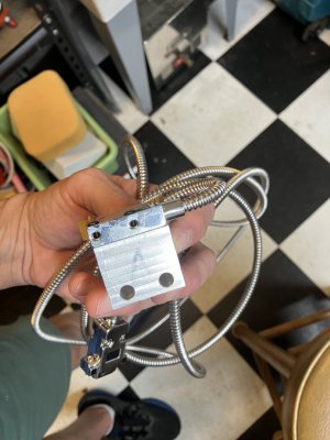
Had a few hours to drill more holes...M6X1.0 this time for the display mount. I'll be able to test out and position the X axis sensor bracket and after some uncomfortable hours of hand drilling I should have the X-axis complete and on to removing the old table dial indicators.
Attachments
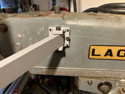
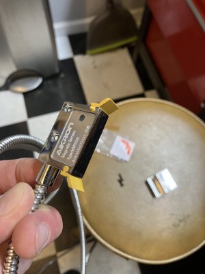
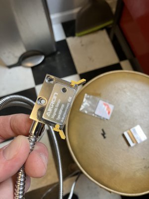
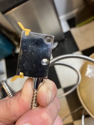
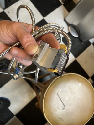
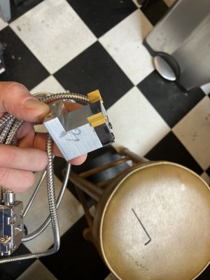
I mounted the sensor to the block and mocked up again with a clamp. Worked flawlessly....more holes to drill. 
Attachments
- Joined
- Jun 12, 2014
- Messages
- 5,068
When you are all done I would check the accuracy/linearity of the scales using 123 blocks or similar measuring blocks. Yuri and others have reported issues (linearity as opposed to repeatability) of some of the Asian magnetic scales like Ditron and those sold through AliExpress. I use ones from Electronica and have not had any issues, would be worthwhile to know which camp the Aikron magnetic scales fall into.
I know the existing travel dials are not a reference like a gauge block, but a few quick checks against my decent axis, X, and they are in agreement. Good point about repeatability. I'll have to perform a few "user acceptance" tests once I have all the components installed.When you are all done I would check the accuracy/linearity of the scales using 123 blocks or similar measuring blocks. Yuri and others have reported issues (linearity as opposed to repeatability) of some of the Asian magnetic scales like Ditron and those sold through AliExpress. I use ones from Electronica and have not had any issues, would be worthwhile to know which camp the Aikron magnetic scales fall into.
One thing I'm realizing that a DRO installation's significant cost is the TIME to carefully drill all the needed mounting holes into the mill. Epoxy is starting to sound better and better ") I have started drilling holes for the Y-sensor mount, hope to be done with Y this Labor Day weekend. The dial indicators came off over the weekend. There was a ton of chips from years of use in the crevice of the Y-travel bar and knee- stuck in place
I have started drilling holes for the Y-sensor mount, hope to be done with Y this Labor Day weekend. The dial indicators came off over the weekend. There was a ton of chips from years of use in the crevice of the Y-travel bar and knee- stuck in place
Question: I wasn't pushing to install the Z-axis now, but I'm thinking it might be wise to finish out with the 3rd dimension. Carefully looking at the area around the knee's slide there isn't a lot of parallel surface space. The sides of the mill appear to taper together, upward toward the ram. Do any of you have decent photos of scales mounted for the Z-axis, mounted on the knee? Seems like a few custom height standoffs might be needed to true up / mount well.
I have started drilling holes for the Y-sensor mount, hope to be done with Y this Labor Day weekend. The dial indicators came off over the weekend. There was a ton of chips from years of use in the crevice of the Y-travel bar and knee- stuck in placeQuestion: I wasn't pushing to install the Z-axis now, but I'm thinking it might be wise to finish out with the 3rd dimension. Carefully looking at the area around the knee's slide there isn't a lot of parallel surface space. The sides of the mill appear to taper together, upward toward the ram. Do any of you have decent photos of scales mounted for the Z-axis, mounted on the knee? Seems like a few custom height standoffs might be needed to true up / mount well.
- Joined
- Jun 12, 2014
- Messages
- 5,068
Do custom standoffs and a beam to support the scale. I often use a slot and small set screws in the sides of the bream to the mounting blocks to set the parallelism in all 3 axis. Magnetic scale alignment do not need to be spot on like glass scales, they can take quite a bit of misalignment before you get reading errors (at least with Electronica/SRA scales). Some examples below, I used the side of the VFD cabinet, but could also mount against the mill body with standoff blocks. I do use chip guards on the magnet scales, even though mine have wipers.


- Joined
- Dec 21, 2018
- Messages
- 2,163
I made aluminum stand offs attached to threaded holes in the casting. I used the threaded holes and a couple of bolts to get the standoff measurements. That way I could just thread the bolts in until the head was the same distance from the knee slide, Parallel to. And make the stand offs to match.
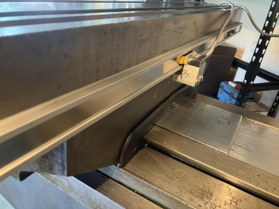
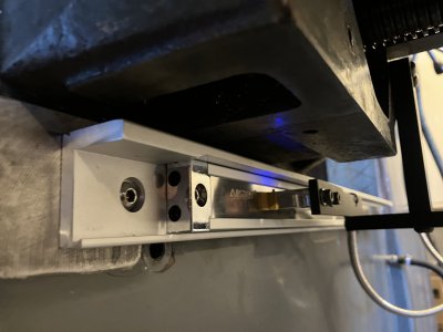
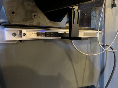
I had time to get the Y-Axis done over the labor day weekend and very happy how things are turning out with the Accu-Rite spar bar and brackets. For those following closely, the spar bar that I thought I found for the X-axis fell through (Ebay), but still on my mind.
I still have to find some 7mm cable stays, fab a chip guard for X, and get to Z on a rainy day.
over the labor day weekend and very happy how things are turning out with the Accu-Rite spar bar and brackets. For those following closely, the spar bar that I thought I found for the X-axis fell through (Ebay), but still on my mind.I still have to find some 7mm cable stays, fab a chip guard for X, and get to Z on a rainy day.
Attachments
Last edited: