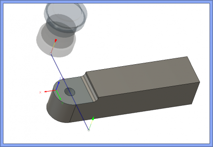
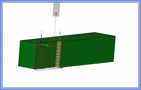
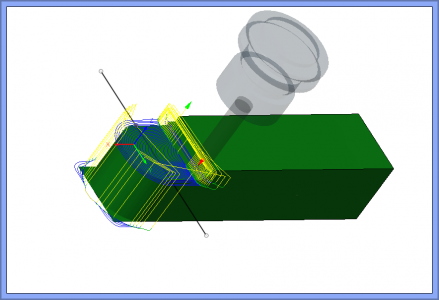
Here is a real world TRACE tool path. I made a measuring error on the flywheel for my tube polisher project and of course transferred that measurement to the drawing without double checking. No real problem, but I need another 1/8'' clearance in the pinion gear housings.
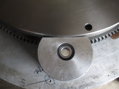
I need about 1/8 more clearance here.
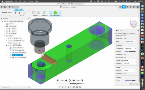
The left side is what I have now, the right side is what I need
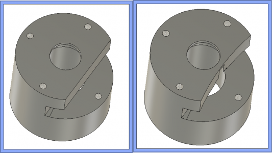
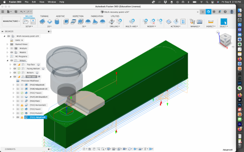
There are several ways to do this, but I chose the simple method and will be cutting some air. I could have constrained the adaptive clearing with a bounding box to reduce the air cutting, but I'm not in that big of a hurry and air chips are easy to clean up.

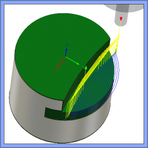
Then I decided to make a final 0.020 contour pass to finish cleaning up. I could have just set the adaptive clearing to leave 0 stock and not even done a finishing pass, but what fun is that. But when I tried to do a 2D contour it insisted on taking a cut all the way around the part rather than just the face I wanted to cut. I could have constrained a 3D contour with a sketched bounding box, but I insisted on making it do what I wanted with a 2D cut.
This is where TRACE comes in. First I drew a 13.5 dia circle, then offset the the circle the radius of the 3/8'' endmill (0.188) from the surface I want to machine because the tool center line follows the trace line. Then drew the two cut lines where I wanted the endmill to start and end, then trimmed away the rest of that circle. So now I have a tool path to follow exactly where I want to cut.
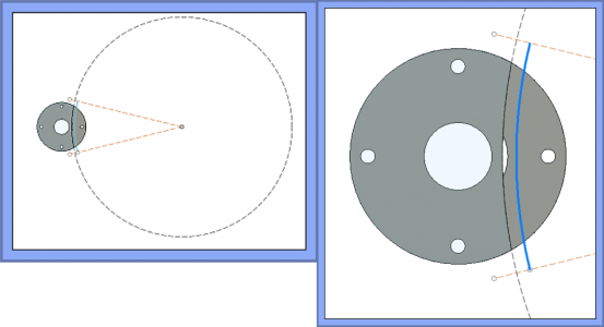
So now all that is required is to go into CAM, select Trace and select the line. Since the line is at the top of the part, I also needed to set the axial stock to leave at -0.645 to reach the bottom of the area I want to cut because the trace function cuts exactly on the line unless you tell it otherwise. You also can use multiple step downs if desired.
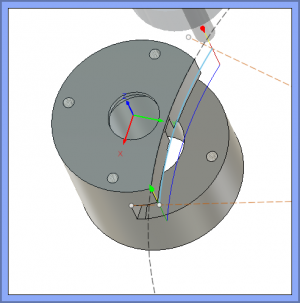
Now I just need to go make some chips.


