I would tackle this as most have said before if you only want to use a mill.
1. Face both sides to thickness.
2. Drill holes.
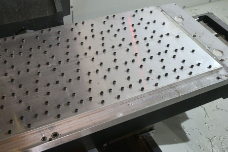
3. Drill tapped holes in sacrificial plate + one reference hole in the centre for future use.
4. Screw the blank to the plate and press go.
Very close to the way I'm doing it.
Check the drawing for the tolerance on the thickness, you may be able to use stock thickness material and skim the faces - only if machining is required on the print. This will give you the edge when quoting as you will save 2 operations and maybe 10% on material cost. It may be worth a quick call to the client to establish the importance of the 1" dimension.
In this case this is for in-house use so the 1'' is a ''suggestion''

It will actually be a bit thinner, like about 0.995 or so.
Quick tip. Always drill the parts befiore making the fixture. This way the fixture can be left in position ready for production.
We drill parts on the fixture all the time, just be very careful of the drill depth so not to screw up the threads in the fixture.
If I had access to a lathe then I would consider starting with tube and facing/chamfering to thickness and roughing out the counterbore within a couple of mm. Then drilling the holes on the mill. And finishing on a fixture as above.
The work could be done on the lathe, but I'm too lazy to stand there and do it.

The method chosen all depends on variables such as material cost / time / machine availability / quantity etc...
Larger quantities will lend themselves to multiple fixturing.
Absolutely. Given this is a 1 off, for an in-house project, I have a lot of flexibility.
This sounds like a fun game, I'll play!
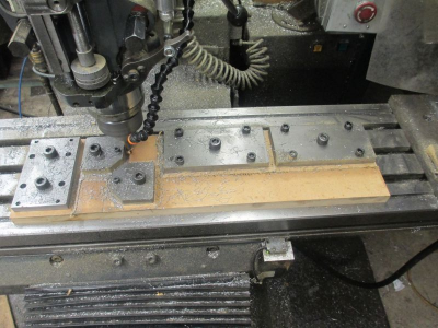
1. clamp stock to table on sacrificial spacer (MDF) with clamps that do not interfere with the interior feature. ensure that MDF has roughly corresponding hole in center for step 3 clamping
2. Mill the interior feature
3. Relocate clamps to inside of part ensuring that they do not interfere with exterior feature. Move clamps one at a time so part does not shift and clamps to not obscure drilled hole locations
4. Mill exterior feature and drill/tap holes
This is the time to use an aluminum spacer. I gave your method, using MDF, some thought, and in this case the process can be simplified by bolting down to a scrap aluminum piece.
So here is how I'm doing it. This is not the only or best way, just how I decided to do it given what I had to work with.
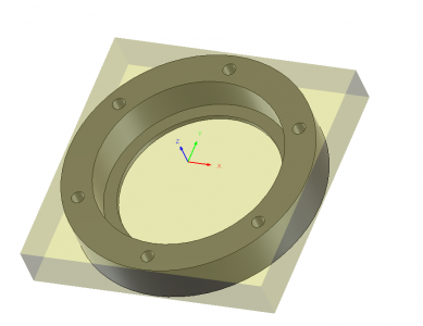
First a quick video of the simulated operation
First the fixture plate. I found this on the aluminum shelf, was a fixture plate for another project. Roughly 6x6x0.5
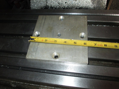
Mount it up in the vice and roughly locate the center hole. The hole is about 0.377, so a 3/8 dowel pin in the drill chuck makes a good center finder.
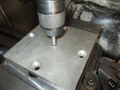
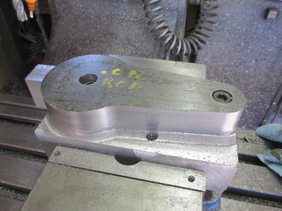
Face and drill & tap the 5/6-18 mounting holes. I can only use 4 of the 6 holes because the existing top & bottom countersunk holes are roughly in line with the part holes. If four 5/16 cap screws won't hold the part then I'm doing something wrong.
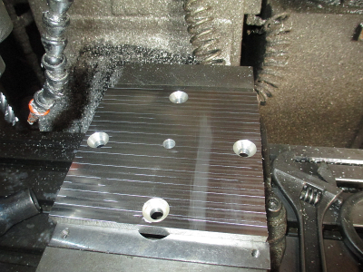
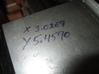
Next locate a fixed point that won't change during machining. This way if you have a power fail or otherwise lose zero, then you can easily recover. I used the top, right corner of the vice, and wrote down the DRO position. Z 0 is the top of the part, so is easy to reset.
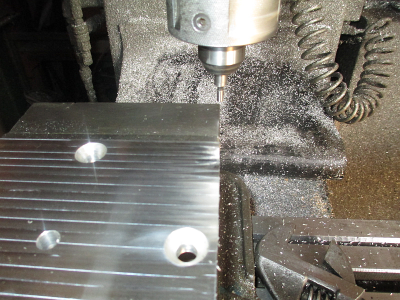
X/Y coordinates of the top corner of the vice relative to 0/0. A vice movable jaw makes a good scratch pad for a Sharpy.
Center up by eyeball, precision is not required at this point, +/- 1/16 or so is close enough. Plenty of excess material to remove. Clamp to the fixture plate and drill the six 5/16 holes 1.050 deep. This puts the drill point through the material, but doesn't damage the previously threaded holes in the fixture plate.
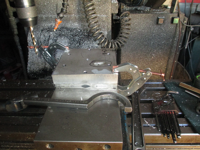
Now take a skim cut on the face, about 0.005'', using a pocketing routine. Now we have a flat surface to work from and that face is complete. That divot in the lower right (not the one circled in black, the one below it) of the picture is what we commonly call a ^%(&&#*


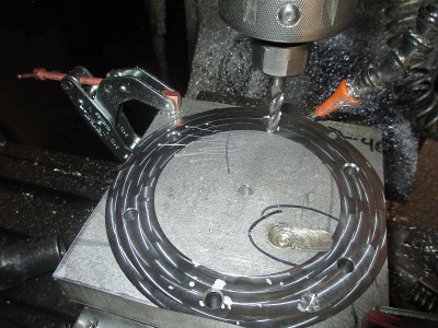
Now bolt the part down and remove the clamps, in that order. Now is ready for the rest of the operations.
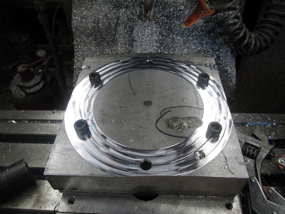

 It will actually be a bit thinner, like about 0.995 or so.


