-
Welcome back Guest! Did you know you can mentor other members here at H-M? If not, please check out our Relaunch of Hobby Machinist Mentoring Program!
You are using an out of date browser. It may not display this or other websites correctly.
You should upgrade or use an alternative browser.
You should upgrade or use an alternative browser.
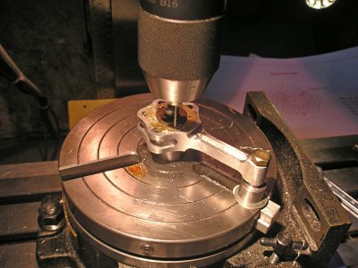
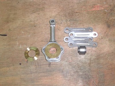
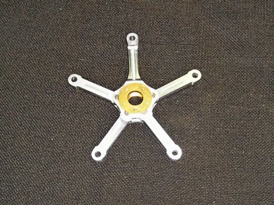
OK so now we can assemble the rod and links , and pop it into the case just to see what it looks like ???
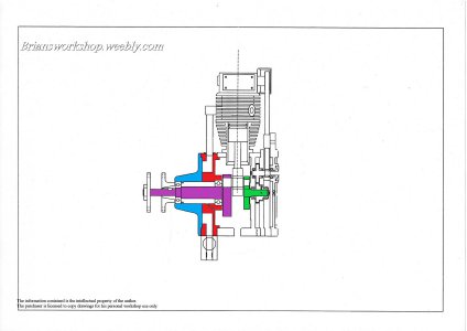
I must stress that the Big end bearing is on the accessory shaft with a dummy pin, as yet we do not have a crank shaft . To go any further we now need the front case and nose piece, This is a little more complicated because the front case contains the inlet manifold ring.
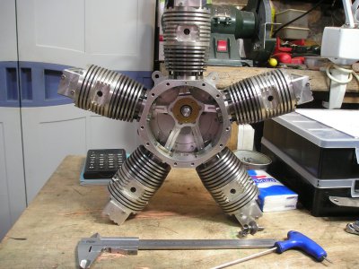
Brian
I must stress that the Big end bearing is on the accessory shaft with a dummy pin, as yet we do not have a crank shaft . To go any further we now need the front case and nose piece, This is a little more complicated because the front case contains the inlet manifold ring.


Brian
Last edited:
So moving on I feel I must go back to when this project started and remind you that the work relies
on two jigs one for the case and the other for cylinders heads ETC
The rotary table and the face plate have a 12mm centre location and 3 screws that are matched to the jigs.
The case jig also has a conversion ring that changes the jig from female to male.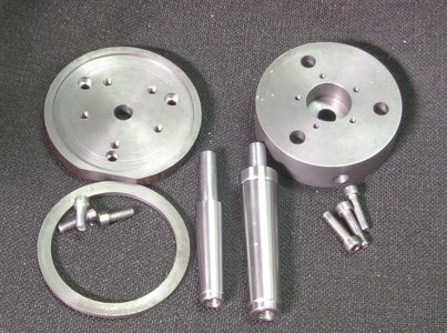
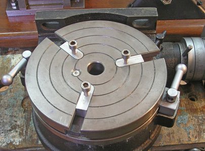
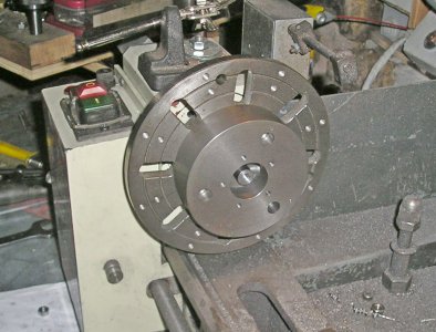
Just for those new members to realise that all the case joints are the same DIA male or female
Brian.
on two jigs one for the case and the other for cylinders heads ETC
The rotary table and the face plate have a 12mm centre location and 3 screws that are matched to the jigs.
The case jig also has a conversion ring that changes the jig from female to male.


Just for those new members to realise that all the case joints are the same DIA male or female
Brian.
The new delivery , material for the front case and the crank shaft.
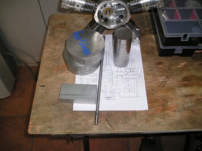
So off we go-- First find centre then mount on the mill and locate the dot.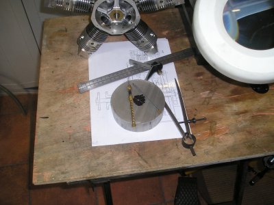
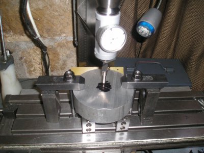
Next drill and ream 12mm to match the jig mandrel.
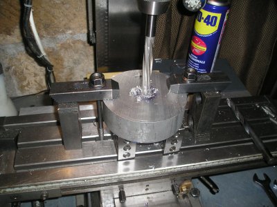
Mount on the face plate using the no3 morse/12 mm mandrel and turn the register for the jig.
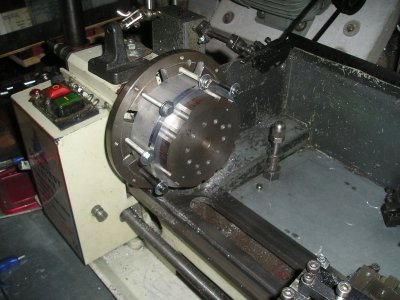
Flip the jig and work over and retain the work with a draw bar,
Bring the blank to the correct OD and machine a male register on the face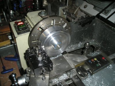
The work is now ready to go to the mill.
Brian.

So off we go-- First find centre then mount on the mill and locate the dot.


Next drill and ream 12mm to match the jig mandrel.

Mount on the face plate using the no3 morse/12 mm mandrel and turn the register for the jig.

Flip the jig and work over and retain the work with a draw bar,
Bring the blank to the correct OD and machine a male register on the face

The work is now ready to go to the mill.
Brian.
Very impressed with your machining. Thanks for sharing.
Watched the video on the first start and cringed when I saw you walking around the spinning prop. But this is obviously not your first rodeo so I hesitated to mention anything. Still, it would make me happy to see a flywheel instead of the prop spinning so close to your person.
Watched the video on the first start and cringed when I saw you walking around the spinning prop. But this is obviously not your first rodeo so I hesitated to mention anything. Still, it would make me happy to see a flywheel instead of the prop spinning so close to your person.
OK next centre the RT with the 12mm mandrel and zero the table.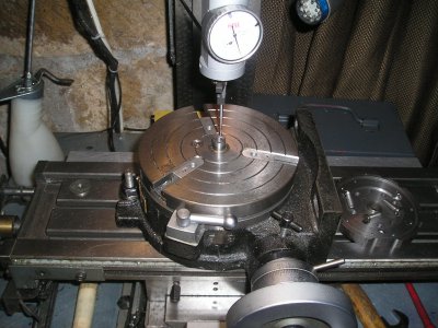
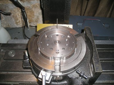
Fit the jig note the master pin at 0° this is also the position of No1 cylinder
Remove the pin, put the work back on the jig with a draw bar, move off to the radius of the master pin
and drill the locating hole, insert the pin now we can go round and drill the case fixing holes.
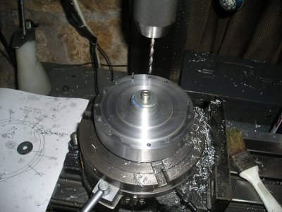
The work and the jig can now be transferred to the face plate and the location for the inner crankshaft bearing
machined.
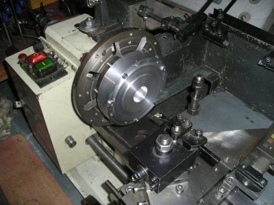
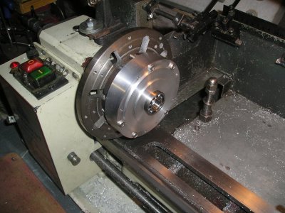
The next operation will be to form the manifold ring.
Brian.


Fit the jig note the master pin at 0° this is also the position of No1 cylinder
Remove the pin, put the work back on the jig with a draw bar, move off to the radius of the master pin
and drill the locating hole, insert the pin now we can go round and drill the case fixing holes.

The work and the jig can now be transferred to the face plate and the location for the inner crankshaft bearing
machined.


The next operation will be to form the manifold ring.
Brian.
Moving on we now return to the mill to rough form the annular manifold.
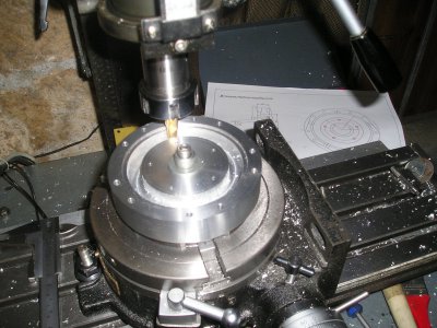
Guess what then its back to the lathe, this time the case fixing holes are used to hold the work.
A boring tool was used to finally bring the manifold to size first the outer edge then by moving
the cross slide over and putting the lathe in reverse the inner edge was done.
A register was cut to locate the closure ring and its O rings.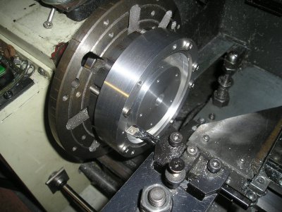
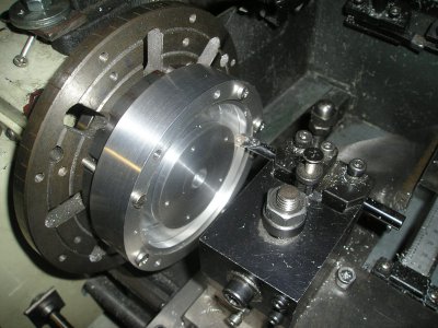
Manifold closing ring in place.
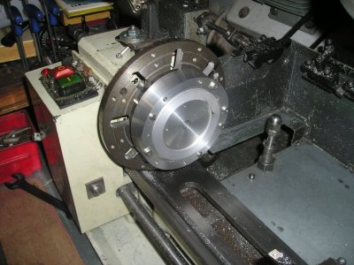
Back to the mill and drill and cut the positions for the transfer tubes.
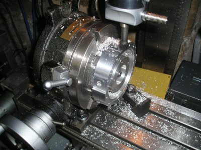
Trial time.
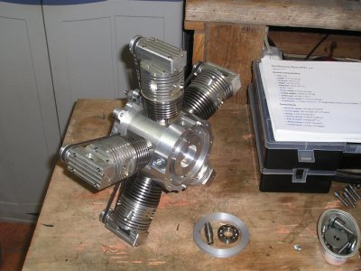
Unfortunately I don't seem to have photos of making the nose piece so here is the part assembled on the case.
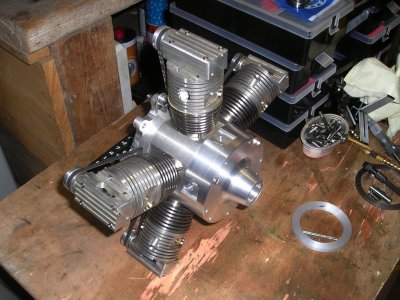
Next part ? The Crank.
Brian.

Guess what then its back to the lathe, this time the case fixing holes are used to hold the work.
A boring tool was used to finally bring the manifold to size first the outer edge then by moving
the cross slide over and putting the lathe in reverse the inner edge was done.
A register was cut to locate the closure ring and its O rings.


Manifold closing ring in place.

Back to the mill and drill and cut the positions for the transfer tubes.

Trial time.

Unfortunately I don't seem to have photos of making the nose piece so here is the part assembled on the case.

Next part ? The Crank.
Brian.
Last edited:

