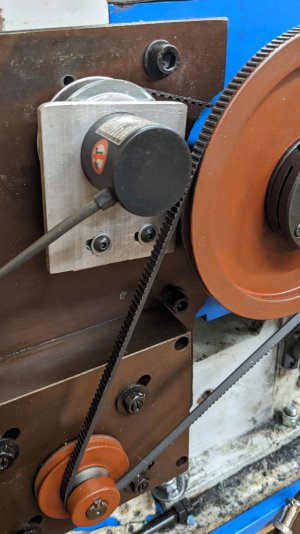
ELS Conversion on Weiss 1127

ivel03

H-M Supporter - Gold Member
H-M Supporter Gold Member
Joined
Dec 6, 2021
Messages
244
I have started the conversion of adding an ELS onto my lathe. Here are some pics of the progress:
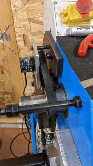
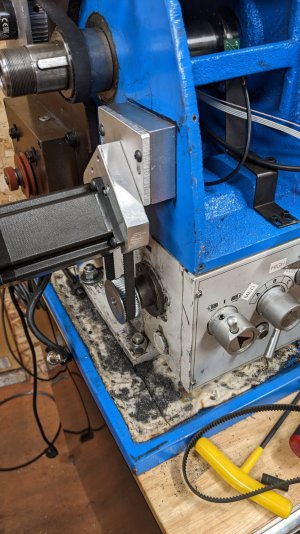
PXL_20221231_220636947.jpg PXL_20221231_220630183.jpg

I'm happy with the stepper motor mount - it is very rigid. I plan on doing a bit more fit and finish on the stepper mount. The encoder mount i'm redoing b/c the bracket kicks slightly sideways, the bracket is way larger than it needs to be and i don't like it - oh and i thought of a much easier way to build it after i completed it.

Excuse the mess - i'm sure many have been in this situation mid-project.
 
very nice!
i'm looking forward to seeing the progression
 
Any reason why the wider belt for the encoder? If anything, I would think you would want a wide one for the leadscrew and a skinny one for the encoder, seeing as how the encoder requires little power to turn it
 
Last edited:
Any reason why the wider belt for the encoder? If anything, I would think you would want a wide one for the leadscrew and a skinny one for the encoder, seeing as how the encoder requires little power to turn it

Good question. The existing 40 tooth gear on the spindle is compatible with an M5 belt. That width for the encoder belt was the first one that i came up with that was compatible with the components.

The belt is temporary for the stepper motor - i have a 15mm wide belt coming to replace that. I didn't realize i ordered narrow belts for the stepper motor - i had swapped the pulleys a few times.

I did a SWAG on the belt lengths and ordered a few of each as i didn't know the exact lengths as i didn't have the pulleys or anything yet. Some of the guesses were highly scientific - based what sizes others used while looking at pics to see if it looked proportionally the same as my lathe! :)
 
Last edited:
I figured you might still be in the prototyping phase
 
Thanks so much for the Photos. My lathe does not have the hole in the casing either. I like the way you mounted the stepper motor. I will use that on mine. Much better than mounting it out front.
 
So far, it's looking good! Since the motor is in a different configuration, might have to fool around with rotation sense, but that's easy to accommodate. When I set mine up, it took a little bit to realize that some changes would be necessary. My first setup cut left hand screws initially! I mounted a marker in a tool holder and watched the spiral form and was puzzled until I realized it was left handed...
 
I figured you might still be in the prototyping phase
Definitely in the prototyping phase. It's easy to get confused when you add and remove many pulleys and belts from your cart to get all of the components compatible with each other.

For those following along - i mentioned in another thread that the PM 1022/1030 lathes have a whole in the casting where you can stuff the motors in there as does many Grizzly lathes but unfortunately the end of mine is solid. I assume that webbing adds some rigidity so i didn't feel comfortable cutting a big hole in it so i had no choice but to mount it pointing out. This will necessitate a modification to the cover and be the most noticeable change in appearance of the lathe. This will be similar to the implementation that @ttabbal did on his 1127.

I rebuilt the bracket for the encoder but i'm not that happy with it still. I have seen that some folks have created a far end support for the encoder shaft b/c of bearing life or fear of a "heavy" pulley spinning on the shaft. Is this a real concern? The 40 tooth T5 pulley is fairly heavy proportionally to the entire weight of the encoder.

I'm waiting on the scales to arrive and i have to assemble the power cabinet. I'm not sure how i'll attach the scales to my cross slide to get them as far as i can out of the way but i did purchase slim glass scales so hopefully i can mount them without too many compromises. I'm also waiting for the brains of the operation to arrive.
 
Thanks so much for the Photos. My lathe does not have the hole in the casing either. I like the way you mounted the stepper motor. I will use that on mine. Much better than mounting it out front.

I mounted the motor at 45* so that i could attach it with 3 screws. I realize this is likely overkill after feeling the rigidity of mount with even a single screw installed and also looking at how others have mounted theirs.
In case it's not obvious from the pics -
The block mounts to the lathe with 2 screws counter bored to sit below the 1/4" adjuster plate attached to it. There is also a pocket in the middle of the block to allow clearance for the 1/4" adjuster plate that mounts to the motor mount with 3 screws at the top. The adjustment is provided via the slots in the 1/4" adjuster plate. There are some "apprentice marks" on the motor mount bracket that still need some more work with the file - things like turning the hand wheel on the mill the wrong way! :eek: Also notice the top adjuster plate is not parallel with the bracket, this position allows for the most belt clearance from the ears.
 
My scales for the DRO arrived today! All of the major parts are in my possession except for the ELS computer but that will be coming along shortly. I changed the encoder bracket a bit more today - mounting it to the block on the bottom instead of the top gives me a bit more clearance from the drive belt and it adjusts a bit better. At this stage of the game i'm still prototyping and going for function over form. Hopefully i'll be able to figure out how to mount to scale to the cross slide in the least intrusive way possible.

PXL_20230106_010032931.jpg
 
Back
Top