D1-4 Spindle & Chuck Measurement and Setup

Ray C

Registered
Registered
Joined
Nov 16, 2012
Messages
5,596
Hi Folks,

By popular demand, I'll post some information about D1-4 spindle and chuck dimensions which I hope to include various techniques to measure things. We'll need to do all kinds of measuring, use granite plates etc. This will take a few days to get through but by the end, it will show a technique I've been using to true-up chucks so they mount perfectly and repeatably. This is only loosely structured as I'm really low on time these days. -Have 2 paying jobs in the shop and the 9-5 day job is getting in the way too... Hang in there. I promise this will pertain to Metrology using a live example.

Note: I'm not a professional machinist -just a lifelong shop rat that loves this stuff. If along the line, I use incorrect terminology or improvements/suggestions are in order, shout it out.

Regards

Ray


Part 1:

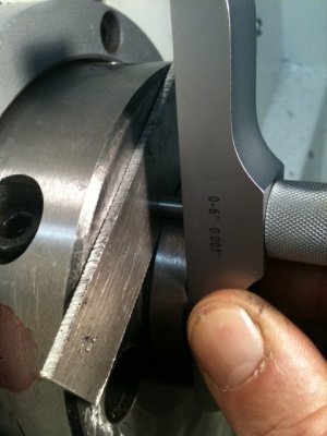
When I recently mounted my old collet chuck on a new D1-4 back, I discovered the back was pretty crude. It would not mount repeatably and closing the locking lugs was next to impossible. Please see the first picture that shows the problem in exaggerated form. There should be no light coming between backplate and spindle face. BTW: I'm demonstrating on a back that's already been properly fitted so, this will show a "sunny-day" scenario of what's going on.

Also, take a look at the PDF. If you have Adobe Reader, you can click the image and rotate it with the mouse. Please note, the faces of the back and spindle nose must contact at the same time the tapered part of the spindle nose contacts the inner race taper of the back. This is a tough geometry to get right -but if you do, your chucks will mount perfectly -every time.

Part 2 coming in the next thread...
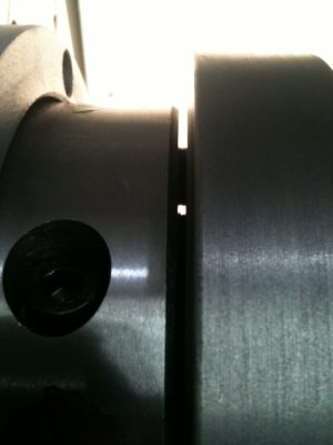
The Problem.JPG View attachment 95507
 

Attachments

  • D1-5-Assembly.pdf
    98.7 KB · Views: 299
Last edited:
Re: D1-5 Spindle & Chuck Measurement and Setup

Looking forward to it! Not to hijack your OP, but by interest is piqued.

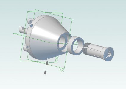
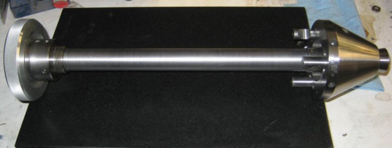
I've made some D1 type attachments for my lathe (a collet closer head and a dog driving plate)... Here's a 3d model of the collet head and a photo of the assy:
Clipboard01.jpg
IMG_1523.jpg
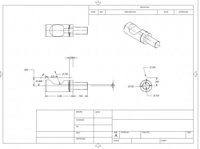
I have a drawing for the camlock pin that I made for anyone's reference. They're much easier to make than one might expect... The threads aren't shown in the dwg...
Cam lock pin drawing.jpg

John

Cam lock pin drawing.jpg Clipboard01.jpg IMG_1523.jpg
 
Re: D1-5 Spindle & Chuck Measurement and Setup

John,

Very cool... And I like the way you inserted the PDF as a JPG. I'll do that from now on. Should have thought of that earlier.


Ray
 
Re: D1-5 Spindle & Chuck Measurement and Setup

Part 2

Word of caution: When you're doing this, make sure your gears are in a neutral/disengaged state and all the safety locks are activated. Nothing here is done under power but you don't want your lathe turning on accidentally while your fingers, hand, head etc are deep inside the cutting area.

As mentioned I'm intermixing a real problem with Metrology. In this case, the problem is easy to see. -The back is crude and doesn't fit. In real life, the space between the faces was about 2-3 thou meaning, the nose taper was bumping into the back taper first and the overall assembly could not sit flush.

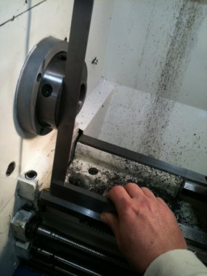
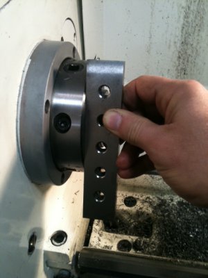
In general when diagnosing a chuck problem, all relevant geometry should be analyzed. First thing I wanted to do is check for gross errors in the spindle. Use a well trusted square, place it on the ways and verify the spindle face is perpendicular to the ways. Rotate the spindle and check in several spots. Square should meet-up flush with the spindle. If something is way off, it needs to be corrected.
Check Spindle 1.jpg

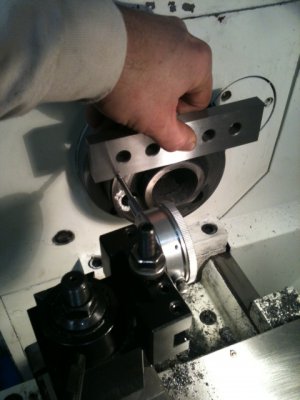
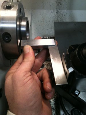
Use a good parallel flat bar and make sure the spindle face is even. No (or extremely little) light should shine through. When I got my lathe, I immediately noticed raised areas around the holes that receive the studs. This was an artifact from the drilling process no-doubt. I used hand tools and very carefully removed the burrs and bumps.
Check Spindle 2.jpg

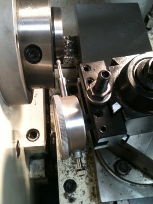
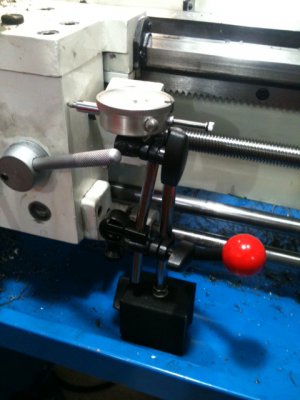
While you're at it, you might as well check to see if your crossfeed is square. Check the DI as you hold the parallel in place and run the x-feed back & forth. If there's a problem, it could either be head-misalignment or crossfeed misalignment. Fortunately, this lathe is dead-on!
Check Spindle n xFeed.jpg


Now, it's a good idea to measure the angle of the nose taper. First, set the angle of the toolpost to match the angle of the nose taper. I used a small square. Metrology Issue: Getting the DI to meet the taper perpendicularly is important. The ball tip of the DI is parabolic -not round. If the shaft of the DI is not perpendicular to the angle, your measurement could be off a thou or two and in this next measurement, we can't afford that. Please see the next 2 pictures to see what's going on. -And I acknowledge, there are other ways to skin this cat but, this is how I happen to approach this and the steps I personally took. Again, other ideas are more than welcome.

Setup Toolpost Angle.JPGSetup Toolpost DI.JPG

OK, moving right along... Now we need a way to measure horizontal travel of the carriage. We're going to measure "Rise over Run" to calculate angle. Put another DI to measure the carriage travel. If you have DRO, more power to you! Here's how I set it up. -Pretty intuitive...

Setup Carriage DI.JPG

Ready for our first Metrology measurement now... Position the Toolpost DI at the tall edge of the nose taper and then move your carriage DI to contact the carriage. Zero the faces. Helps to thump the machine a few times to make the DI's settle-out. Next, move the carriage to the right until the toolpost DI reaches the other edge (low side) of the taper. Measure both DI's. You probably want to do this 4-5 times to make sure your setup is rigid and repeatable. Adjust your mag bases and fixtures for rigidity until you get several readings of consistent numbers.

In my case, the spindle DI gave me 0.025" the carriage moved 0.200". Arctan (0.025/0.200) = 7.125*. Guess what, the D1-4 spec says it's supposed to be 7*, 7", 30s -and that equals 7.125*. So far, the spindle is looking good.

OK, Sasha is extremely bored with this and has decided to rest her head on a pile of laundry to demonstrate (in only a way a dog can do) that it's time to do something else. Not only that, 5:30AM is coming up soon and I gotta sleep fast.

More tomorrow....


Bored Sasha.JPG

Check Spindle 1.jpg Check Spindle 2.jpg Check Spindle n xFeed.jpg Setup Toolpost Angle.JPG Setup Toolpost DI.JPG Setup Carriage DI.JPG Bored Sasha.JPG
 
Last edited:
Re: D1-5 Spindle & Chuck Measurement and Setup

Ok I am now subscribed. So I can ask lots of questions. Some may be dumb. :nuts: First one. I see you are using your PM1236 which is a D1-4 for demo purposes. Are your taper measurements only for a D1-5 or do they work for both?
 
Re: D1-5 Spindle & Chuck Measurement and Setup

Oops. LOL... Another lathe I used was D1-5 and I got the title wrong. Hopefully I can change the title. :thinking:

EDIT: BTW, the nose angles for D-4 & 5 (and all the D-types) are the same. Diameters are different though but everything here custom-mates all the pieces so, getting the diameters right happens by virtue of the process.


Ok I am now subscribed. So I can ask lots of questions. Some may be dumb. :nuts: First one. I see you are using your PM1236 which is a D1-4 for demo purposes. Are your taper measurements only for a D1-5 or do they work for both?
 
All,

I'm going to go back and revise history and change all occurrances of D1-5 to D1-4 to go along with the example. Some might be wondering if the reason my chuck didn't fit is because I had the wrong back. -No, that's not the case. A #5 wouldn't even come close to fitting a #4 spindle and all of the factory supplied backs were maladjusted in the same way. Truth be known, just recently, I mounted several #5 chucks for the prototype shop at work and the two numbers are bouncing around in my head...

I apoligize for the confusion.


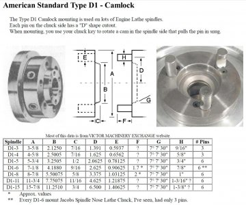
BTW: A quick search of D1 Spindle Dimensions will bring you to a chart like this -which is worth having a look at. http://www.tools-n-gizmos.com/specs/Lathe_Spindle_Mount.html

Ray
 
Great stuff Ray!

Here's a jpg of something close to the link you provided.

D1-Camlock Dimensions.jpg

D1-Camlock Dimensions.jpg
 
Part 3:

For this example, I'll be citing the dimensions read off this machine, specific to this example. You'll need to make your own measurements -don't use mine verbatim for obvious reasons. As you're doing this, take careful measurements. -Triple check yourself. Also, note that some of these pictures are staged -taken tonight even though I did the work a while back. ...Decided to pull a chuck apart to show you guys this because if done right, the results are very rewarding. Since I put witness marks on the chucks, they'll go back together in a jiffy and it only takes a few minutes to center them.

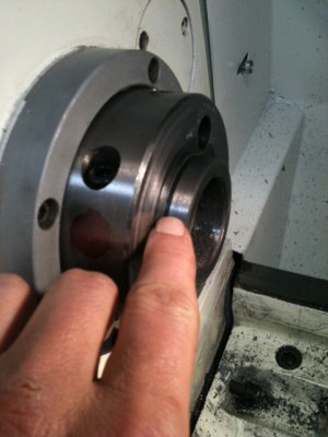
The tapered nose on the spindle is build-up on a shoulder that has a recess. See the gap my finger is pointing at in the picture below:

Recessed Shoulder Taper.JPG

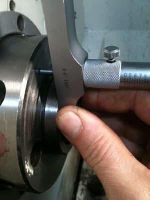
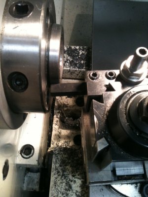
To measure this we'll take low readings from the face of the spindle then, we'll use a shim that butts-up to the very edge of the wide part of the taper. Admittedly, this is a little dicey but, I couldn't think of any other way to do it. I got lucky and found a piece of scrap that to the best of my eye, came right up to the edge as needed. If anyone can suggest a better way of making this measurement, I'd be glad to hear about it. To make the measurement, you could use a depth gauge or, you could use a DI mounted on the spindle provided the DI has enough throw to gap the distance. Turns-out, the differences indicated a gap space of 0.100". See the setup below:

Shoulder Depth 1.jpgShoulder Depth 2.JPG

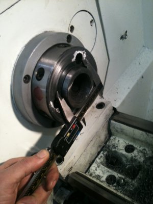
We also need the diameter of the wide part of the taper. That's easy enough. It turned out to be 2.475". See below:
Measure Taper Base Diameter.JPG


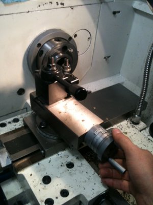
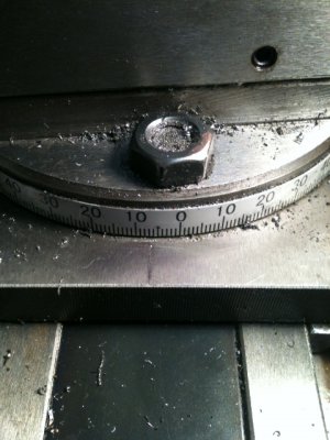
Next, we need to setup for the cutting operation and must adjust the compound to the exact angle of the taper. I used the back end of a carbide holder mounted in the toolpost and adjusted the compound, carriage and x-feed until it matched exactly. Back the compound (not crossfeed) in/out until it's an exact match. Even though we know the angle is 7.125*, you can't trust the markings on the compound as shown. My compound showed about 6.9* as far as my eyeballs can read the fuzzy lines yet, using very precise measurements, we found it to be exactly 7.125*. When you set the correct angle, lock down the compound. See the setup below:

Ajust Compound Angle.JPGBack-Forth with Compound.JPGIndicated Value.JPG


OK, almost ready to have some fun.... In the next part (coming tonight) we need to flatten the back then cut the taper. See you in a while...

Recessed Shoulder Taper.JPG Shoulder Depth 1.jpg Shoulder Depth 2.JPG Measure Taper Base Diameter.JPG Ajust Compound Angle.JPG Back-Forth with Compound.JPG Indicated Value.JPG
 
I made a chuck adapter several years ago that had to have the taper nose on it for an A-20 mount. It was 26" in diameter with a 12-1/2" ID hole in it. The register diameter was 16.250" diameter. All I had to measure it with was a veriner caliper. It must have worked, the customer never blinked an eye over it.
 
Back
Top