Current Project

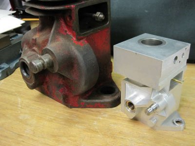
Thanks Bazzz. I have a full size 6S that I have restored to running condition which I hope to be able to display next to the 1/2 scale model. Doing that while building the model helped out a lot and was of course the basis for the plans as well. I always liked the little Maytags too!!

Bill
 
Here's a few more photos of some additional work on the pulley side of the crankcase. Its coming along slowly, but still coming along.

Bill

Crankcase 004.jpg Crankcase 005.jpg Crankcase 003.jpg
 
Last edited by a moderator:
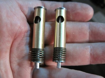
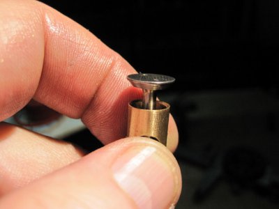
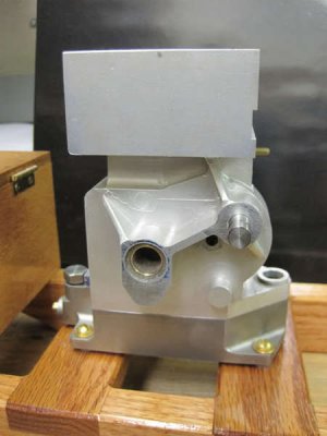
The end of last week saw a bit more progress on the crankcase and this weekend I got the valve cages done at home on the sherline equipment. Below are a few pictures of the additional progress.

Bill

IMG_0577.JPG IMG_0570.JPG IMG_0571.JPG IMG_0576.JPG
 
Last edited by a moderator:
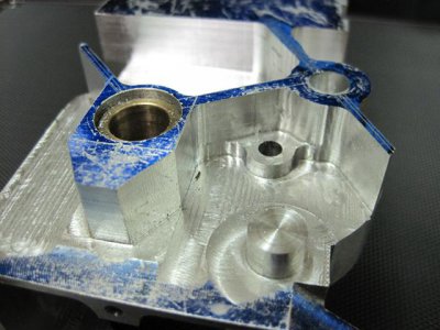
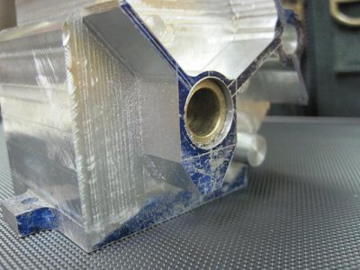
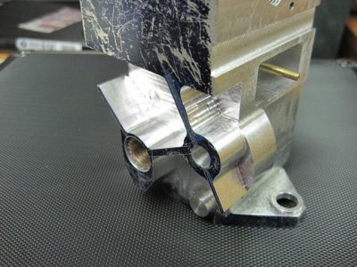
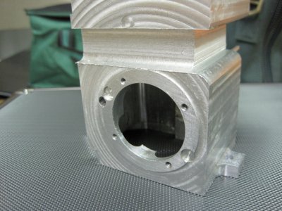
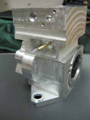
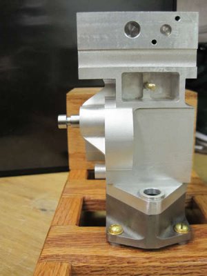
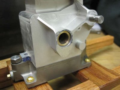
Yet a little more progress on the crankcase, in this installment the reinforcing ribs have been angled and smoothed out and that side of the crankcase has been lightly bead blasted to remove the layout dye and to begin removing some of the machining marks. The balance of this work will wait until the top section and fins are cut in order to give the whole part more of a casting look. I knew this was going to be a bugger when I started and it hasn't disappointed, but amazingly enough I still haven't killed it yet and its looking more and more like the original as well. Here are a few pictures from this latest progress.

Crankcase001.jpg
Crankcase002.jpg
Crankcase003.jpg
Crankcase004.jpg
 
Awesome work! What's the trick to making the decals? Are they just print-on decals like made by Testors?

John
 
John. Thanks for looking in. The decals were an experiment that in this case worked out pretty well. I found some clear 8 1/2" x 11" labels at the office supply store which are made of a mylar film rather than paper. I had previously purchased a set of reproduced decals for the full size engine the model is scaled from so I had a facsimile of the original B & S decals. The only trick was to get them drawn and scaled to 1/2 the original size once printed. To save on label cost I laid out 6 of each of the 3 separate decals to fill up the page. That gave me 6 sets of decals should they ever wear out , etc. So far they seem to be holding up well to rubbing, etc. but not sure how they might react to gas oil even though they should not be subject to that much of it. As I recall the layout was done in AutoCadLT and then each image was transferred to a Word document and copied. The printing was done on an HP color laser printer.

Bill
 
The color laser should work well. I've used HP color laser toner as resist for PC board etching using Ferric Chloride.

Here's another technique that comes to mind since you have original decals. Simply scan them, shrink 'em, and print them on decal paper. I've used the stuff from Testors and it's pretty nifty... http://www.testors.com/product/0/9198/_/Custom_Decal_System I made some reproduction dial indications for an antique Grundig radio I was restoring.

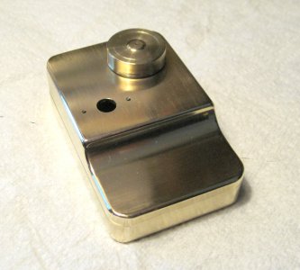
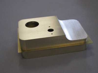
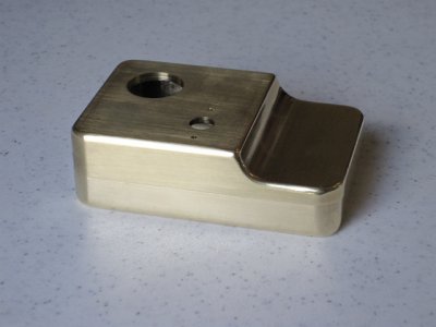
Again, awesome work. I wish I had the time, patience and, above all, the skill to do what you're doing with manual machines. I'm dumbfounded by the fuel tank. Can you give us a brief rundown on the machining of that beauty?

John
 
Thanks John,

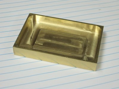
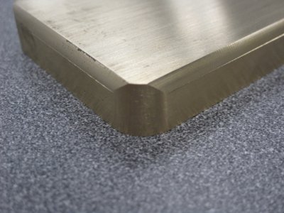
The gas tank was made from 2 pieces of brass which were then soldered together with a thin piece of brass between them to replicate the seam welded joint of the original tank with was just thin die stamped steel. Obviously that wasn't practical for a one off model. All of the routing out on the inside ot the top and bottom parts, as well as most of the contouring of the outer edges (rounding of corners, rounding of edges, etc.) was done prior to soldering the two halves together. There was a LOT of filing, hand sanding and polishing as well until I was happy with how it looked. While I haven't weighted it, I would guess the model tank weighs as much as the original full size tank and then some (probably even with the original tank half full of gas :) ) I have included some pictures below which may show the progression of it's construction. By the way, the model gas tank cap does not screw on, but rather seals over the filler opening riser via an o-ring...one of the few deviations from the original.

Gas Tank 002.jpg
 

Attachments

  • Gas-Tank-004a.jpg
    186.8 KB · Views: 14
  • Gas-Tank-005a.jpg
    228.6 KB · Views: 9
  • Gas-Tank-007a.jpg
    181.7 KB · Views: 8
  • Gas-Tank-001a.jpg
    156.7 KB · Views: 6
  • Gas-Tank-006a.jpg
    188.2 KB · Views: 14
Last edited by a moderator:
Here is a .pdf of one of the two plan pages for the gas tank which also shows the the riser and gas tank cap.

Bill
 

Attachments

  • BS6S-Gas Tank 2.pdf
    59 KB · Views: 15
Last edited by a moderator:
Back
Top