Collaboration on a 3D printed threading dial for a SouthBend 9C

Are you looking to do mold patterns as well ??

Is that aimed at me?

If so, what do you have in mind? Patterns for green-sand casting? Patterns for "lost-plastic" casting?
What rough sizes? Do 3D models already exist for the patterns?
What kinds of scaling (for metal shrinkage) and drafts are required?
It sounds interesting.......

-brino
 
Sorry for the delay on response Brino, but yes, I am doing some sand casting experiments with my homemade foundry set up
and was curious about the possibilities for making patterns.
I was thinking about split molds, as in printing up half of each side and locating them on a center board aligned properly for ramming up the 3d pattern in sand like the case for a power file or such, I can make patterns out of wood in the old school style but this looks to be an easier way labor wise but at this time out of reach for me financially. as for shrinkage specs There are charts for calcs. by type of metal used and also for draft angles, my old foundrymans manual seems to be hiding from me at this time.
I haven't tried lost plastic molding or wax and Styrofoam yet but it is finally getting warm enough to work the sand out in the shop
so I will be squeezing in some casting time in with the forging and machine work, as well as the gardening, seems like I'm doing more work since I retired then I did when I was employed ...........
 
Last edited:
OK. I finally got all the hardware I needed to go ahead and put the thread dial that Brino printed up for me together. Keep in mind nobody has ever accused me of under-building anything as I have a tendency to go a little overboard and possibly overthink things sometimes.

So I started this project by running a 5/16" reamer through the main body of the printed thread dial to clean the hole up and smooth it out. I don't know what size the printed hole was supposed to be but it worked out as though it was meant to be reamed 5/16". Simple operation on the drill press. I bought a 3' stick of 5/16" 12L14 and it was a tight fit in the reamed hole so I chucked the rod in the lathe and started working it down with some 220 grit sand paper. Got a real good fit.

Next piece was the attachment between the carriage and the thread dial. I am a little leary of the strength of the plastic holding enough tension with a set screw so I drilled and tapped all the way through the boss and pin to make sure that the dial should not be able to easily rotate (like I said, I overthink this stuff).
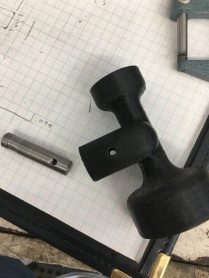
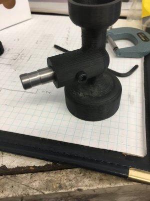
IMG_6330.JPG
IMG_6331.JPG
I had the same concern on attaching the gear to the shaft so it too was drilled and tapped all the way through to make sure it couldn't slip on the shaft. I also did not ream the ID of the gear or the dial itself but instead turned down each end of the shaft to make a tight fit on the gear and a not as tight slip fit on the dial. The dial end of the shaft got a flat filed in it for a set screw. I figured there is no strain on the dial so a set screw should be very adequate for that end and it gives me a little end play adjustment for the whole assembly. As for the dial part I had to turn the OD down a few thousandths because it fit pretty tight in the housing. I just put it on the shaft and tightened the set screw then set the compound to approximate the angle of the edge of the dial (it's actually a little curved but the angle worked fine) dialed it in in the 4 jaw and took a pass off it.
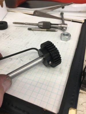
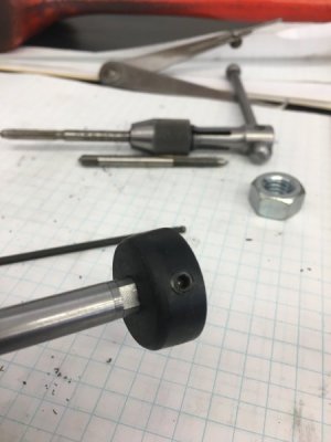
IMG_6337.JPG
IMG_6339.JPG
I chucked the body of the dial in the 4 jaw and used a boring bar to clean up the inside of the bottom of the housing where the gear rides. The printing was rough here from the support material that gets removed after printing.
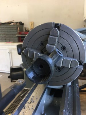
IMG_6332.JPG
Final assembly and adjustment and it seems to work so far. I'll change some gears, grind a tool bit and try to do some actual threading tommorow and report back. Gear engagement looks pretty good.
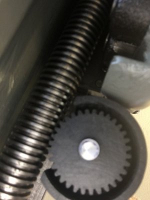
IMG_6344.JPG

Again many thanks to Brino for printing and sending me the parts. I will probably paint the body to match the lathe (although the black doesn't look to bad) and paint in the numbers and lines.
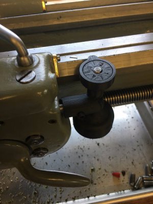
IMG_6342.JPG
 
Keep in mind nobody has ever accused me of under-building anything as I have a tendency to go a little overboard and possibly overthink things sometimes.

There's nothing wrong with doing things well!
It looks really good.

The angle of your last picture with it installed shows the numbers and lines really well.....better than I remember when looking straight on.
Have you figured a way to try a high-contrast paint on the letters and lines?

Remember if the PLA wears we can try again in ABS......in fact I just got some grey ABS filament that might match the lathe better.

-brino
 
I was actually thinking of cutting/grinding a tool to widen and deepen the grooves a little (do a little engraving) then see what I can do with painting them.

I originally planned to put a brass "thrust washer/bearing" under the gear but taking a pass with the boring bar smoothed the body up enough that I think it will do fine. I thought that maybe the plastic might create enough friction to cause a problem but I don't think it will be turning fast enough to matter.
 
Last edited:
MrPete has a video where the fellow who created the 3D files for carriage dials suggested using white silicone caulk to fill in the lines. MrPete tried this and found it worked the best. The excess wiped off the dials better than paint.
 
I'd like a set of dials but sounds pretty hard when YA don't have a fancy plastic squirt gun machine. Yes I know it's program like cnc. More things I never got into doing . Looks like nice alternative if your lathe don't have a threading gage . Good job it turned out really well.
 
I'd like a set of dials but sounds pretty hard when YA don't have a fancy plastic squirt gun machine. Yes I know it's program like cnc. More things I never got into doing . Looks like nice alternative if your lathe don't have a threading gage . Good job it turned out really well.


If you have designs already made, various people are willing to print them for you. You would need to provide STL files from thingiverse etc. or a CAD file in some cases might work. Almost any 3D CAD will export an STL these days though and any printer user will know what to do with them. So you don't need your own fancy plastic squirt gun if you don't want to get one.
 
Played with the thread dial this evening and found a little mistake I made. The flat I put in the shaft for the dial should have been "indexed" to the lead screw. I find that I do not engage right on the numbers or lines. It engages either right before the line or right after (about the thickness of the line away). I think I can just refile the flat a little further around the shaft to fix this. Should have assembled and checked the engagement before I just randomly filed. Wasn't really thinking about it. :dejected:
 
Back
Top