- Joined
- Apr 30, 2012
- Messages
- 2,401
It has been awhile since i have added anything to this thread and I finally have a project I think will be interesting and challenging to add.
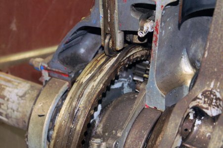
I was recently contacted by Bill Gruby about assisting him making 2 parts for his 18 cylinder Radial engine build.
( ADD Bills thread here )
I was a bit puzzled by Bill's request because if any of you know Bill he is very interested in Cnc but honestly doesn't need it to accomplish
the many things he builds and shares here in the forum. I have yet to see anything he could not make and was sure he could make these parts.
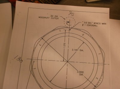
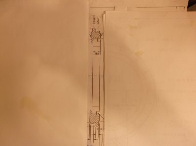
Bill mailed me the prints for the 2 cams for the engine and the directions for machining them manually that were included with the plans.
The challenge became immediately apparent as I read the directions and imagined myself trying to follow them and what my end results would have been.
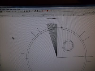
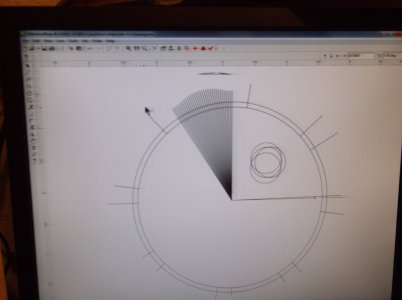
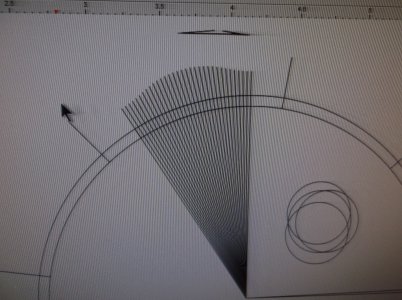
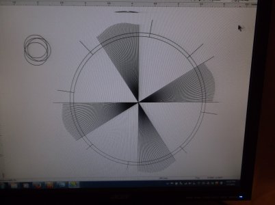
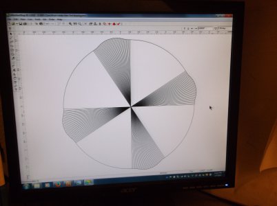
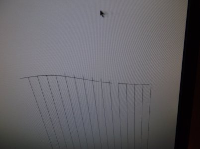
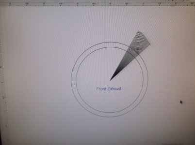
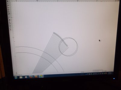
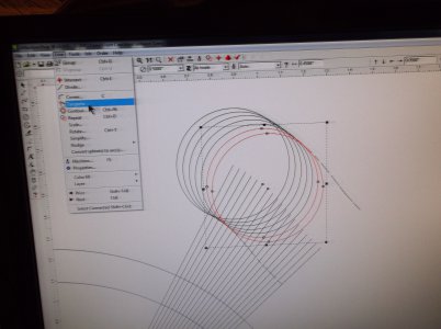
To just machine out the cam lobe profiles on on the rotary table there would be 280 separate 1 degree moves of the rotary axis and the Y axis that
have to be at the same time, meeting at the same end point to ensure a good finish. you would have to keeps in mind the machines backlash and reset the dial to zero for each change in y axis direction.
that is a .001 to .003 move in y and 1 degree of table movement 280 times to complete 8 cam lobes. and there are 2 of these cam rings.
If you tried to move one axis then the other the finish on the part would be a series of very small steps around the entire profile that would need to
be finished smooth by hand when done.
reading each line of the directions then preforming the move without any mistakes and not getting a headache would be beyond anything I have ever done.
one mistake and the part is scrap and there are 2 of these that need to be exact to run right.
anyone who knows 4 stroke engines and the effect of any changes to a camshaft have on performance would see the problem here.
these cams can be made and the motor will run but the difference is in how smooth and steady the motor runs can very a lot.
this is a real determining factor in how all the work to everything else made comes out in the running of the model engine.
So with all that said how will I do this on a Cnc 4 axis mill is the next question and the answer was not as easy as I expected.
there are different types of 4th axis functions and most wont work for this part.
In most 4th axis setups on a Cnc mill the rotary axis is mounted standing up facing the z axis from one of the four opposing directions available
X+ X- Y+ and Y-.
Different types of cam software's do different types of operations from different locations of z to the axis. z axis centered behind or in front of the
center of the rotary axis is used to make things like gears.
for my examples the rotary axis is mounted on the left side of the x axis facing z.
for the setup I just described the x axis moves back and forth as the y axis increases the depth of cut and z doesn't move.
when each operation at that location completes y backs out from z the the rotary axis turns to the next location and repeats the operation.
this is 4th axis indexing and can be done with z above or to the side of the center of the rotary axis.
This operation will not work for a cam lobe.
the next type of 4th axis operation is called wrapping.
wrapping takes a drawing that is in x y plane and converts all the y or x moves ( determined by the rotary axis location )
into rotary axis rotation at a given circumference. if the y or x axis length 2" then you will wrap that around a circle with a circumference of 2".
z is lowered on each line and follows it at one set depth. raising and lowing to cut each line.
This will not work to cut a camshaft.
the next type of rotary axis operation is rotary axis turning. in this operation the rotary axis rotates and the cutter removes material at a set z depth,
like a lathe operation.
this won't work for a cam lobe.
the next operation is rotary axis contour turning
in this operation the rotary axis rotates and the z axis moves up and down and the x axis side to side as the part is rotated
this can make a cam lobe but only with a ball end mill and the finish would be a series of lines around the cam as the cutter moved in x direction.
this would be smoother than hand making the part and more accurate but would still have to be hand finished.
you can't cut the profile in one pass with a flat bottom end mill eliminating the ridges a ball cutter would leave because the flank side of the cutter
as z moved down would cut
into you lobe as it lowers.
If I did do it with the ball end mill and decided the finish would be acceptable to polish out, the end mill would have to be less than an 1/8" because the
cam lobes in each row are that close to each other.
this will not cut bills cam to the desired result.
so to do this with a standing rotary axis to a close to desired result the y axis will have to move also so the cutting surface on the flat cutter moves
from center to flank as the z axis lowers and face to center as the z axis raised and the cam lobe rotation crosses center. since the
face and flank shape of the cutter contacting the lobes will be concave and the lobe would have to be cut by stepping in from the side in small increments
to keep from leaving lines like the ball end mill.
this software for for this type of 4th axis operation is very expensive and I don't have it.
this is Not an available choice for bills camshaft from me.
Since 2006 I have tried demo software's whenever available and I have never seen the 4th axis operation I need for this project
I want to cut with the side of the cutter so the cutter will not leave lines around the circumference. one finish pass at a set depth from start to finish.
to do this the rotary axis has to be mounted on the mill table facing up centered with z axis and all the moves to make the lobes have to cut in
either y or x direction away from zero.
the reason I haven't seen this approach to rotary axis is because a Cnc milling machine can cut this shape without the need of a rotary axis. by moving x and y in any direction
it can cut any shape. makes sense right.
well not for Bills cams.
on Bills cams as your looking down on the print there are undercuts that come in from the sides with the part mounted in this direction.
the cutter has to step in from the side below the upper cam to cut the lower cam.
I'll have to cut this from the side with a Woodruff key seat cutter.
problem solved? well almost. true I can set the z height to the correct cam lobe height then with the software I have move in and cut the cams Outside diameter by moving the x and y axis until I have moved all the way around the part, lower z and repeat for the next cam shape.
then move out and up to clear the upper lobe.
a little hand coding and it could be done that way.
well not with my machine and mach3.
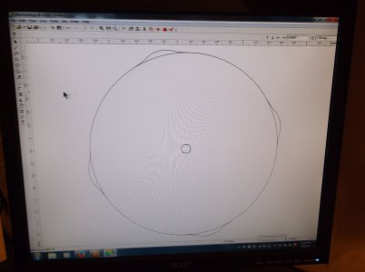
mach3 backlash compensation works perfect in a linear move but has trouble working in an arc. I have .0015 backlash in x and in y.
the end result will be four or more bumps in the surface of the cam where mach3 compensated for the backlash.
where to go from here...
I have it figured out and I know how to accomplish what I need to do but I'm tired of typing and will post how I'm going to do it and show what I am doing in another series of posts with pics and maybe videos .
Thank you for viewing
Steve
Last edited:

