Cast concrete lathe base

I've used 3d printed change gears (super oversized) successfully. Not as much load. Might work...

Arrange your thrust load to pull the spindle into the headstock!

Sent from my SM-G892A using Tapatalk
 
I actually also printed a change gear for myself lol. A 63 tooth for more accurate metric threading. Worked well to machine a longer cross slide lead screw for an extension. Printed it out of Taulman nylon 910 and it's more than strong enough.

I did think about simply angling the teeth in the right direction to pull the sliding gear to the outsides. The problem is when I'm running the lathe in reverse, the axial thrust would switch directions and cause the sliding gear to tend toward the center, out of alignment.

If only herringbone gears could be shifted into place like that, they're just as easy to print haha.
 
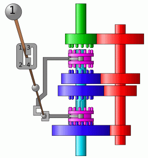
You know what? I don't need the gears to slide around. The shafts have a keyway running the full length of the gearbox, so I can just print four stationary herringbone gears and a gear selector collar. Essentially this image I got off wikipedia, but two speed instead of four.
Gearbox_4gears.gif

Oh boy I'm getting excited now lmao. I'll make a new thread if (when) I do this.
 
I’m sure there are some super polymer types for 3-d gears. I know I’ve read some impressive things with metal 3-D printed items which are then oven treated. Very cool stuff.
But that’s the total amount of “Learned“ knowledge on my end with printed gears and such.
That said, I did order an eBay thread gauge for my South Bend lathe. The 3-D g ar was pure junk. It just started to shed plastic as I used it to thread items. I made a copy of the thread gauge out of aluminum in which I did use the printed thread gauge as a model. I made a Delrin gear for it. My thread gauge has performed perfectly
 
Just found this thread searching for tips to the same thing. How's the concrete base working out?

Can you post a photo or describe your hardware solution for mounting & leveling the lathe on the block? I'm having a mental block about how to use the threaded holes in the lathe bed and still provide adjustability. Likely a simple solution I'll smack my forehead upon seeing, but my brain's in limp mode.
It's been working out pretty well, I'm definitely glad I made the base. All I'm doing to level the lathe is shimming under the feet to get the twist out. I find this more stable overall than trying to use gravity when my wood workbench warps slightly with the weather and the weight of the lathe isn't enough to twist itself much anyway.
 
Realized I didn't answer the question about how the lathe is actually mounted. You can see in the first post's photos how I cast some long bolts into the concrete that serve as studs for the lathe's feet to be fastened to. Definitely weld some rods to the bolt heads to spread the load so they don't just crack the concrete if you do this too.
 
Got it. For some reason I thought the holes in the lathe base were threaded, but this makes perfect sense.
 
I really like what you did with the concrete base. I too made a concrete lathe table for my Atlas 10F. However I might have overbuilt it a little after seeing yours.
 
I knew a fellow who mounted a couple of Craftsman (Atlas) 12" lathes (about WWII vintage, basically F10'a with a taller headstock and tailstock, plus the compound built taller to raise the tool post) in concrete. When I say "in" they were actually imbedded in concrete!

Harry built a pyramid for the headstock, and one for the tailstock. He bridged between the two pyramids (about 2' x 2' at the base) with a trough. In pouring the concrete, it filled the forms for the pyramids, and filled the trough. The top of the pour was above the level of the feet, and was part way up the bed itself, just leaving room for the carriage to travel. The concrete completely filled the center web of the lathe bed, leaving no place for the swarf to go.

He had to clean out the swarf constantly, as it would bind up the carriage if left to build up.

This made the lathes incredibly rigid. He put large motors on them and used a roller chain drive. He had a contract to make 3/4" Acme adjusting screws, 1/2 right hand and 1/2 left hand. He was cutting the Acme threads in three passes!
 
Back
Top