Burke No. 0

Managed to find some time between trips to do a little more work on the spindle locking arrangements. As previously noted, there should be two locking nuts behind and two in front of the rear bearing. Of the four, only one was present on the machine - in front of the bearing. Unlike the portion of the spindle behind the bearing (which is completely threaded), the spindle in front of the bearing has unthreaded space available forward of the threaded portion. Because of this, I was able to make a bronze collar as backup for the existing nut instead of a second nut. No threading required, you see - just a drilled and tapped hole for a grub screw which rests against the unthreaded portion of the spindle. In this way I avoided damaging the existing threads with the grub screw. Because there is minimal thrust, this grub screw probably won't need a locating point drilled in the spindle.
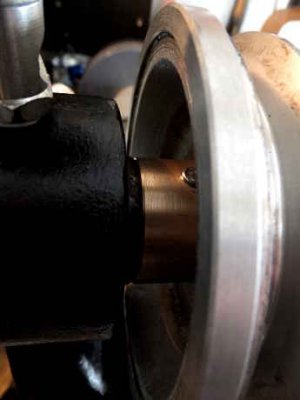
rear spindle collar.JPG

rear spindle collar.JPG
 
Back for a couple of days before my last trip away for the Summer...

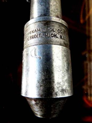
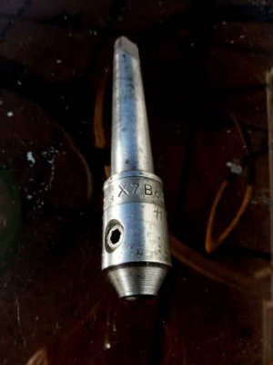
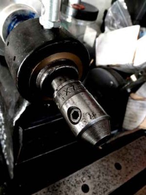
Mike (aka Ulma Doctor), who has contributed comments higher up in this thread, very kindly sent me (from California) an endmill holder to fit this machine. Made by the Putnam Tool Co., Detroit, Michigan, it has a B&S #7 taper and holds a 3/8" endmill. It's a cool vintage piece of tooling which really suits the machine and has tons more character than the set of import collets I bought. Here it is:

endmill holder 1.JPG endmill holder 2.JPG endmill holder in situ.JPG

Cheers Mike! :thanks:

Now, I might even be able to make some progress with the rear spindle locking nuts before I go away again...

endmill holder 1.JPG endmill holder 2.JPG endmill holder in situ.JPG
 
Woodtickgreg and Ulma Doctor - thanks for the like and the thanks.

Now, at last, the rear spindle locking nuts which have been keeping me awake at nights...

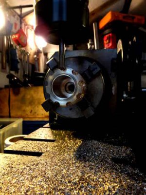
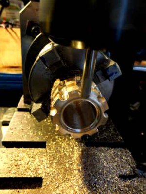
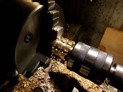
I went for a splined (I hope I'm using the term correctly) thumb-nut kind of approach (due to the minimal level of thrust which they will bear), and to achieve this - after roughly boring out some brass stock on the lathe - once again called upon the services of the good old Dore Westbury, which I have come to love:

milling splines.JPG milling splines 2.JPG

Rocking the rotary table, dancing with the dividing plate, then back to the lathe to part off the two nuts:

parting off nuts.JPG

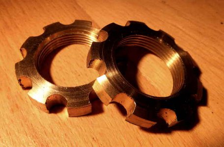
These were the easy bits. However, due to what my daughter refers to as a 'rookie error' in measuring the spindle thread and an elusive final bore, cuttiing the threads was a bit of a mission. However, my trusty tap came up trumps in the end, resulting in the final nuts:

rear spindle locking nuts.JPG

They fit the spindle. I just hope they remain locked together in the right place at speed...

When I come back from my trip away I plan to faff about with stainless steel washers to try to find a satisfactory but easy way to minimise friction against the bearings.

Cheers guys :))

milling splines.JPG milling splines 2.JPG parting off nuts.JPG rear spindle locking nuts.JPG
 
Last edited:
Back from my travels.

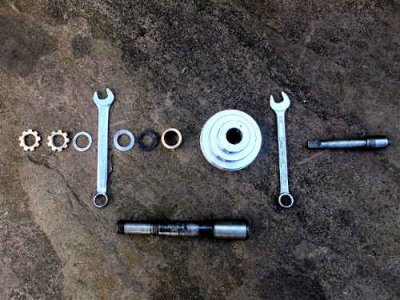
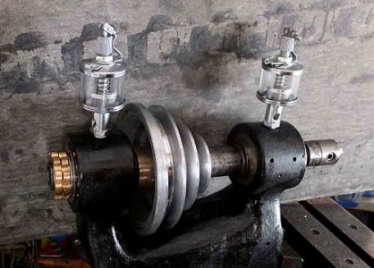
I bored and turned two steel washers to size and gave the pulleys a polish. All of the components for the spindle are now complete. Here they are, disassembled but laid out in the correct order. The spanners represent the plain bearings. Left is the back, right is the front end. So, from left to right we have: 2 brass locking nuts, a steel washer, the rear bearing, a steel washer, an original steel locking nut, a bronze locking collar with grub screw, the pulleys, the front bearing, an endmill holder. Below that lot is the spindle itself:

spindle components.JPG


Here is the completed spindle, assembled and in situ on the machine:

spindle in situ.JPG

I have taken quite a bit bit of advice to get me to this point, and I see no reason why this arrangement shouldn't work. However, my plan is to keep it like this until I have tested it out under power. As you will see in due course, it will be quite some time before I do this...

Meanwhile, the next thing is the drawbar...

spindle components.JPG spindle in situ.JPG
 
Many thanks, guys. Very kind of you.

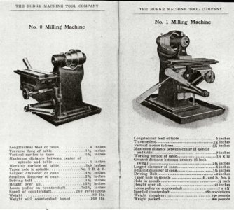
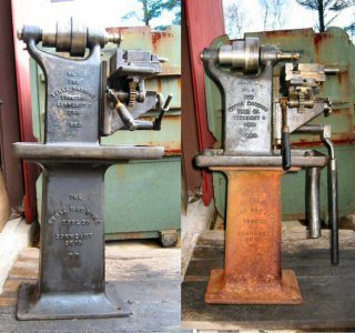
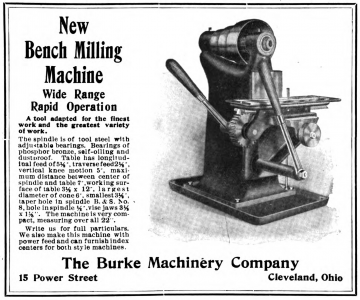
Nels - interestingly I just read Mick's blog earlier today via another forum. It's very impressive, and what a fine machine. There is however sometimes some confusion as there are two different horizontal mills that are commonly called the Burke No.1. One of these is the one Mick has, which I believe is actually a U.S. Machine Tools No.1 but often gets called a Burke because the two companies later merged. The other Burke No.1 is a small horizontal benchtop mill pretty similar to the No.0 but a little bit bigger, as shown in the first picture of catalogue pages below. The second photograph shows - I believe - two No.1's on stands. The third image - another catalogue page - is interesting because the machine looks like a No.1 but the dimensions are different from either the No.1 or the No.0 as specified in the first catalogue pages. The catalogue also locates Burke in Cleveland, Ohio, while the raised lettering on the two in the photo (and on my No.0) places Burke in Conneaut, Ohio. This change may have something to do with the merger with U.S. Machine Tools but I have no idea what this machine is. It may be a different version of the original Burke No.1, but it definitely isn't a U.S. Machine Tools No.1 like Mick's. If you are reading this and you know, please feel free to put a post about it on this thread.

Burke_miller_0_and_1_small.jpg Burke_no_1_mills_small.jpg

modern-machinery-v017-n05-1905-05-p0231-img0239-burke-bench-mill-ad-crop-1460x1218.png Burke_miller_0_and_1_small.jpg Burke_no_1_mills_small.jpg
 
Last edited:
Back
Top