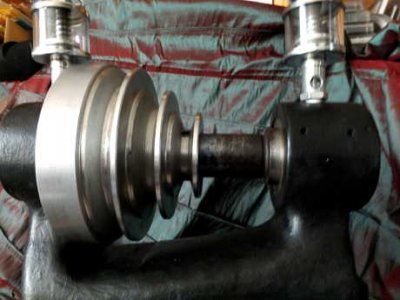
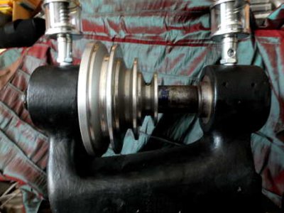
Burke No. 0

Hi Gary, I see what you mean now about the tapers. I was thinking the spindle rode in straight bushings, I also had the front and back swapped! lol
I have a Starke #4 lathe, (early 1900's) and it uses the same type system with a tapered front and a spanner nut at the back, pulleys in the middle.

Your making great progress, keep up the good work!!


Mark
 
Understood, Mark.

Following input on another forum I think that in the original machine there would have been two threaded collars in front of the rear bearing and two threaded collars aft of it.That way you can fine-tune the way that the front taper of the spindle sits in the bearing, then lock it in position. I need to replicate that principle, which shouldn't be too difficult now that I 'get' it.

BTW a couple of other people also had the front and back of the machine mixed up. Very easy to do when looking at photos.

Again, thanks for your positive thoughts. I hope to make a bit more progress over the weekend.

Cheers,

g
 
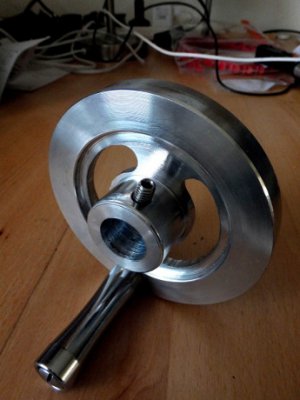
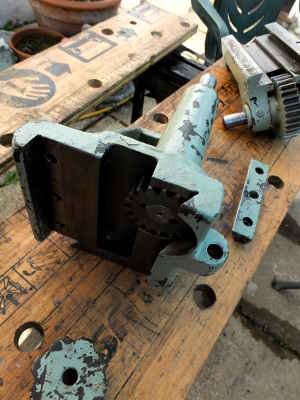
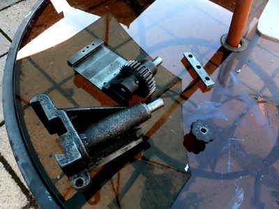
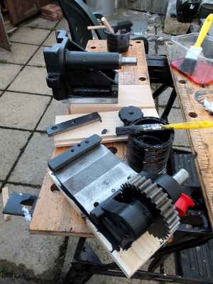
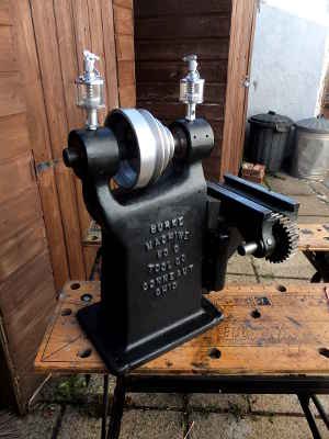
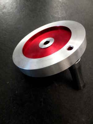
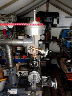
Knee and saddle replaced and trial fit of pulleys. Also, I had a spare handwheel left over from a mini-lathe upgrade a couple of years ago, so I have decided to modify it for the No. 0 so that it can be used as an alternative to the lever feed on the z axis, like the blue mill higher up in the thread. I will of course also keep the lever so that it can be swapped over with the handwheel at any time.

The handwheel will need to be bored out to fit the shaft. It will also need to be faced off because much as I love metallic red, this mill does not require it :shocked:. Neither did the mini-lathe, actually... Might also mill a couple of curved slots in the wheel on the rotary table for funkiness's sake...


kneereplaced.JPG handwheel.JPG

kneereplaced.JPG handwheel.JPG
 
Last edited:
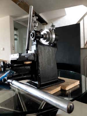
The feed hand levers for the x and z axes: the heads - which are original - were stripped of the old light green paint and painted matt black. I suspect the handles are not original, but they are pretty cool anyway. They are made of aluminium and they polished up nice and shiny. They are also long - each lever stood on end is as long as the mill is high. This is much longer than the single handle which can be seen on the blue example above.

levers.JPG

levers.JPG
 
Here are the levers temporarily attached to the mill in development, just to give a sense of what it looks like:

leversattached.JPG

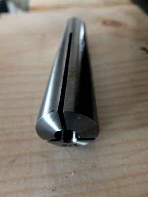
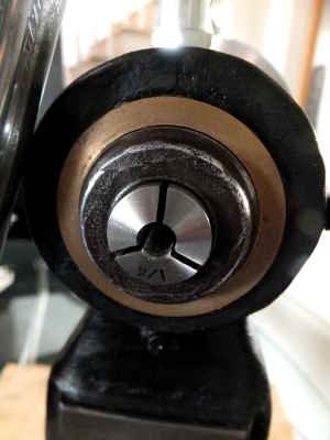
Also, the Brown & Sharpe #7 collets arrived today, all the way from China via America. They are the right size. Yay!

collet.JPG colletsfit.JPG

leversattached.JPG collet.JPG colletsfit.JPG
 
Last edited:
Step pulleys fitted to spindle: three equidistant holes drilled through the bottom of the groove of the smallest pulley and tapped M6 for grub screws. Corresponding locating points drilled in spindle; pulley was then secured with grub screws. It's positioned to give clearance to a Powertwist link belt. This job was done on my Dore Westbury mill, which I bought in May this year and have not long finished restoring. It was the first time I have used the DW. It's sweet! No comparison to the import plastic-geared machine that it replaced...

fitting pulleys.JPG

fitting pulleys.JPG
 
Now on to properly fitting the pulleys.

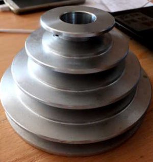
This is the original step-pulley as purchased:

pulleys original.JPG

It was too big to fit the machine, so as shown higher in the thread, I had to get rid of the largest pulley:

pulleys turned 1.JPG

As you can see, this left a plain cylindrical section where the large pulley had been. Initially my intention had been to keep this section as a kind of visual 'nod' to the fact that the machine in its original state would have had flat belt pulleys (though of course the flat section shown here would not operate as a pulley, it was to be for visual effect only). However, I intend to use a Powertwist link belt to drive the machine. Due to the small size of the mill, there is not much clearance between the bottom of the pulleys and the main casting. To prevent the belt from fouling the top part of the main casting, the pulleys have to sit quite far back on the spindle where the gap at the top of the casting is deepest. With the flat section in place as shown above, this was problematic because (1) the flat section overhung the rear bearing and blocked access to the threaded part of the spindle and the inner spindle locking nut and (2) the whole thing looked unbalanced from a visual point of view. I therefore had to turn off the flat section, leaving me with this:

pulleys turned 2.JPG

This now allows access to the spindle locking nut. Also, although it's not too obvious from the picture (due to the camera angle) it looks more balanced as there is a gap of about 1 cm between the back edge of the largest pulley and the front of the rear bearing. That said, the pulleys still sit a bit further back on the spindle than I'd ideally like from an aesthetic point of view. However, while I am using an A-section Powertwist link belt this is as good as it's going to get. In any case, the system should now drive the spindle with a satisfying amount of torque.

pulleys original.JPG pulleys turned 1.JPG pulleys turned 2.JPG
 
Thanks for the likes, guys. Very kind of you.

And now to handwheels - a new one for the Z-axis and the original one for the Y-axis. I took the shiny red handwheel pictured a few posts above and faced it off roughly in the lathe to lose the red. I then milled two curved slots in it using a rotary table on the Dore Westbury, after which I gave it a few finishing passes in the lathe. The bore was then widened to fit the z-axis shaft which controls the rack and pinion lifting mechanism for the knee. Finally, I gave it a polish:
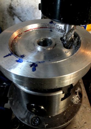
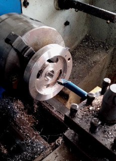
curved slots.JPG boring handwheel.jpg finished handwheel.JPG

Now, in the picture below two things are apparent. One is the condition of the table prior to it being cleaned up, and the other is the way that a previous owner had mounted the existing Y-axis handwheel. A collar - which was too wide for the shaft - had been inserted behind the handwheel. This caused the handwheel to sit too far out on its shaft so that the cap-head screw that you can see in the picture did not sit in the locating point and the threaded section at the end of the shaft did not protrude out of the bore of the wheel:
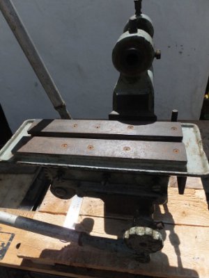
table before.JPG

I replaced the cap head screw with a grub screw and got rid of the offending collar, allowing the grub screw to rest in the locating point. This also gave some clearance to the shaft so I was able to finish off its threaded end with a couple of washers and a domed nut. The picture below shows both handwheels (existing and new) properly in situ. The new handwheel can be easily removed and so can be regarded as interchangeable with the original lever. The boss was already pre-drilled and tapped so I drilled a corresponding locating point in the shaft for a grub screw:
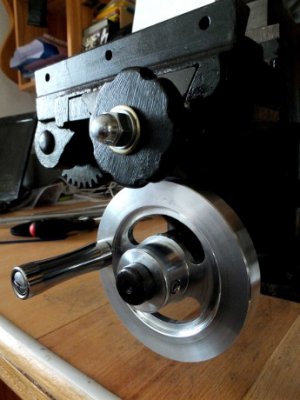
handwheels in situ.JPG

To finish off a good day of progress, I got going on the table with WD-40, Scotch-Brite and sandpaper. A tedious task, it has to be said. The picture below shows the result and that's as far as I'm going to go with it. The machine is possibly 100-plus years old, so why kill myself trying to make it look brand new? IMHO the residual patina looks good anyway. The surrounding table casting will of course be painted black. Incidentally, despite soaking the table in kerosene for two weeks and then drowning it several times in WD-40, I couldn't take it down any further as the screws holding the flat strips to the casting just wouldn't come out without me chewing their heads. I decided just to leave well alone...
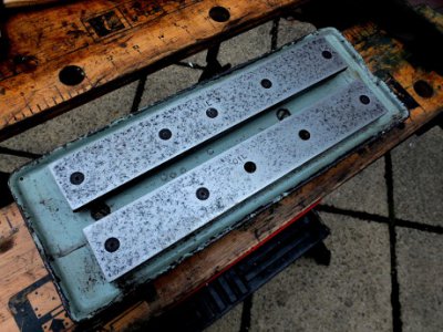
table cleaned.JPG

curved slots.JPG boring handwheel.jpg finished handwheel.JPG table before.JPG handwheels in situ.JPG table cleaned.JPG
 
Last edited:
Back
Top