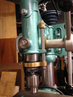
Buffalo No. 15 Drill Press Restoration

The spindle taper repair is a prime candidate for spray metal welding. Shops that repair a lot of shafts can do the work. After the buildup the taper can be turned or ground back to original size. A good job will be visually and structurally the same as new, and it is possible to use harder metals for the repair as well, which is a plus for a machine taper. Price will be a factor with any professional repair of the taper.

The other way to do it is with Prussian blue, fine files, a dial indicator, a GOOD female taper, and infinite patience. It must be round, to size, aligned with the spindle center line, and to the correct taper, all at the same time. It is quite doable if YOU are up to it and do not get frustrated easily and reach for the angle grinder. It will take considerable time. 8^) The spindle will be very slightly shortened by the work.

If the spindle looks like that, the inside of the chuck probably does, too. Putting a buggered chuck on a repaired spindle will not result in a good fit and will damage the repaired spindle. That appears to be a Jacobs chuck. Jacobs usually stamps the arbor taper size on the chuck.

Here is Abom79 doing a spray weld job in a recent video:
 
Last edited:
Again- I'm really glad for the comments! You guys give me lots to think about. In the meantime, enjoy some more progress pics...

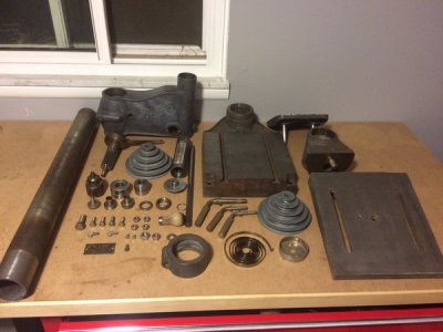
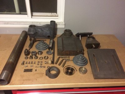
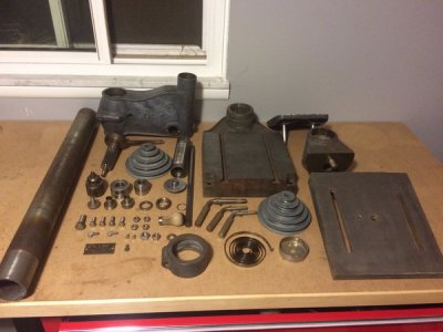
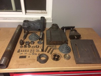
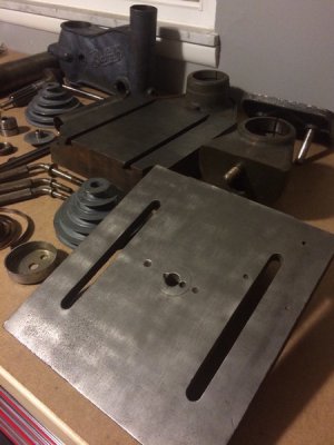
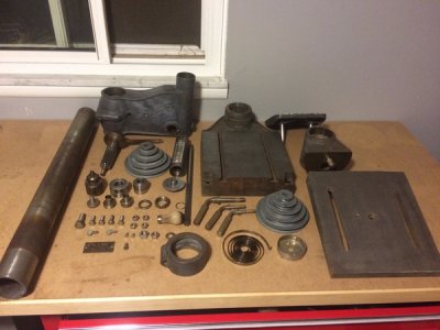
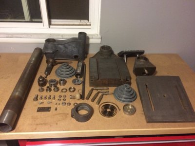
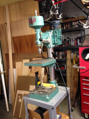
All parts (except for the post) have now been degreased and wire brushed.
IMG_5586_zpsb4ynvhok.jpg

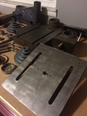
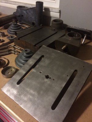
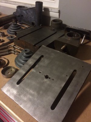
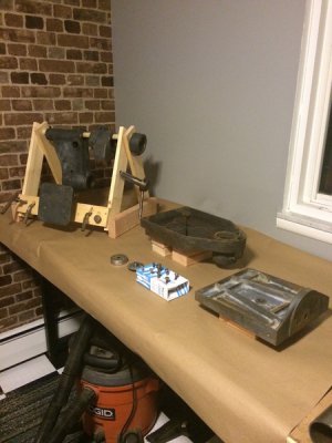
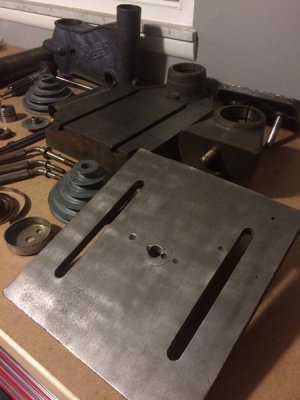
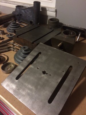
I was able to use a scotchbrite wheel to remove the rust from the base and the table. There is some definite pitting in the table, but overall- it's absolutely useable.
IMG_5587_zpsxcr6p8uh.jpg

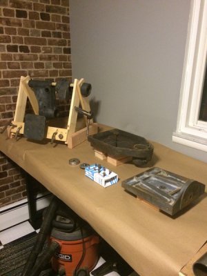
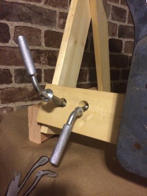
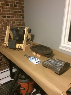
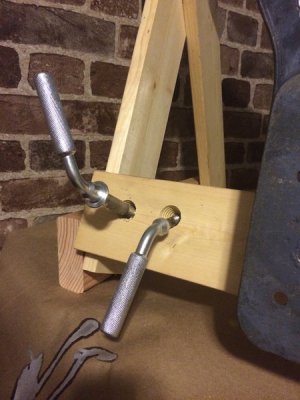
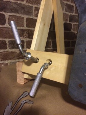
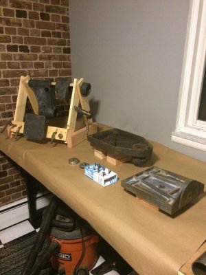
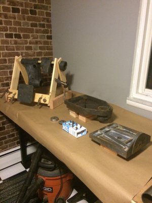
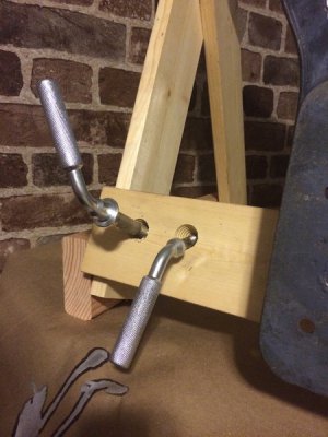
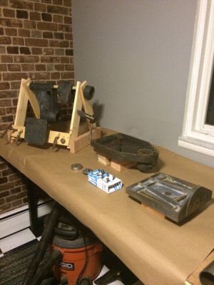
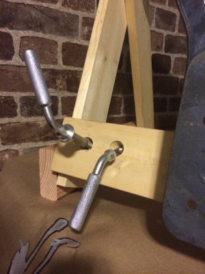
I prepped my bench for paint. I made a little a-frame to hang some parts off of:
IMG_5592_zpsy7ghhh2j.jpg

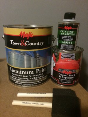
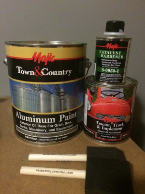
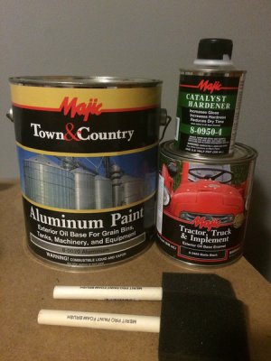
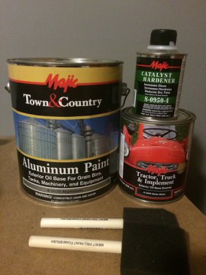
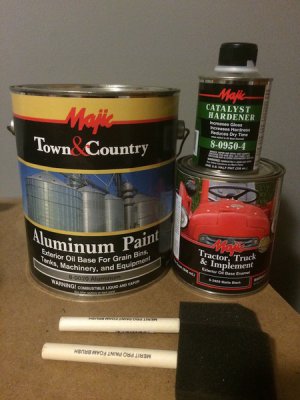
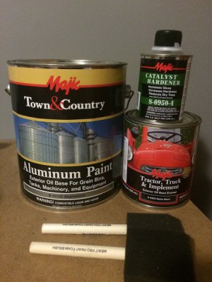
I did decide on the black finish with aluminum accents:
IMG_5589_zps8t1kpquf.jpg

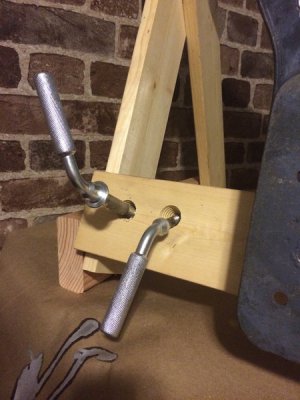
The aluminum paint covers much better than I expected:
IMG_5593_zpsjgz67bm7.jpg

IMG_5586_zpsb4ynvhok.jpg

IMG_5587_zpsxcr6p8uh.jpg

IMG_5592_zpsy7ghhh2j.jpg

IMG_5589_zps8t1kpquf.jpg

IMG_5593_zpsjgz67bm7.jpg

IMG_5586_zpsb4ynvhok.jpg

IMG_5587_zpsxcr6p8uh.jpg

IMG_5592_zpsy7ghhh2j.jpg

IMG_5589_zps8t1kpquf.jpg

IMG_5593_zpsjgz67bm7.jpg

IMG_5586_zpsb4ynvhok.jpg

IMG_5587_zpsxcr6p8uh.jpg

IMG_5592_zpsy7ghhh2j.jpg

IMG_5589_zps8t1kpquf.jpg

IMG_5593_zpsjgz67bm7.jpg

IMG_5586_zpsb4ynvhok.jpg

IMG_5587_zpsxcr6p8uh.jpg

IMG_5592_zpsy7ghhh2j.jpg

IMG_5589_zps8t1kpquf.jpg

IMG_5593_zpsjgz67bm7.jpg

IMG_5586_zpsb4ynvhok.jpg

IMG_5587_zpsxcr6p8uh.jpg

IMG_5592_zpsy7ghhh2j.jpg

IMG_5589_zps8t1kpquf.jpg

IMG_5593_zpsjgz67bm7.jpg
 
He mentioned the chuck being crap, I said he needed a new one in earlier post, spray welding would probably be just as bad or worse for warpage, and I'm not sure using a harder metal would be ideal, being that the chuck may be of harder metal than the spindle itself already which is the perfect setup. Watch the oxtoolco video series on short machine tapers and how he fixes exactly this type of part. It's a relatively easy fix, and could potentially be free for the guy.
I think that build up using tig would have less tendency for warpage because you can get in and get out with the heat, allowing it to cool between buildup welds, and seeing exactly what it's doing, as far as warpage, and knowing exactly where to weld next to pull it over if needed.

His spindle is 5/8 diameter, seems like it would get pretty dang hot with spray welding, I'm not up on that other than watching the interesting videos but with a mig process of spray transfer, that's super hot.....
 
Interesting discussion... I rebuilt a Buffalo 15 floor mount DP years ago and loved it. Great machine. I've got another one now - beat up, abused, and tired - sitting in the shop waiting it's turn to come back to life. So this is a very good discussion, particularly your photos showing components.

So, thinking, another option to repair your taper is simply take the spindle to a shop and just have them grind a new, good taper on the existing end. The process would involve removing a little material along the existing damaged taper until you reach good material all around - removing maybe not more than .030 or so. then face off the end to comply with the minimum diameter measurement needed to mount a new chuck. Grinding produces a smoother finish, resulting in less run out than turning with a lathe. This would shorten the quill by a few thousands, but that is negligable and you would never notice the difference once reassembled.

In any event, one other thing you can do is put the existing spindle, as is, on a pair of centers and run a dial indicator along the length. This will tell you if the spindle is tweaked off the axis or not, and by how much...
 
I definitely appreciate the alternative options, Glenn! Thanks for bringing that to my attention. It's funny- although I've been making things my entire life, although I feel like I can build the things I build without much thought, although I have boxes and boxes of tools, I'm absolutely completely new to machining! I thought my many years of experience in other areas of making stuff would apply (and it probably does) but I am very quickly learning that there is so much that I take for granted in the areas I know about and so much that I simply don't know about in machining! Even down the most basic of the basics: where to get stuff is not something I know. I'm familiar with Enco and McMaster Carr, but I have a feeling these are not the end-all, be-all places that you all shop at. I guess I'm just saying that I'm learning a lot and have a long way to go. So I definitely appreciate you mentioning the alternative option.

...And it seems like a really good option in this case.

So here's another newbie question. How do I ensure a NOS chuck has a clean female taper? I see plenty on ebay, but they almost all have an arbor in them. Is it safe to assume that there's a clean female taper there once the arbor is pulled out? How could you know? Or maybe the only "real" way to know here is to actually buy a brand new chuck.

I'm glad you're enjoying the pictures!! Certainly over sharing is a major character flaw of mine. :)
 
Buy a brand new chuck or have a taper gage, which you can make with proper tooling, importantly a sine bar and the right gage blocks for the taper, when I made my chuck adapter I had to do this, my lathe being a threaded spindle and the chuck I had being a d1-6, I had to match the taper to my adapter to the chuck back, also having the chuck when fitted be in tolerance for runout, which it was....
You could buy an arbor and use it as a gage to spot with
 
chevydyl- I finally got through that whole spindle taper series from oxtoolco tonight. That was super informative... He did mention near the very end of part four that one option for the female taper is to bore a new taper (since you already have the lathe setup) and then cut a sleeve. You'd bore out the chuck and press fit the new sleeve into it. That's a neat idea for sure!
 
Wildo,
Your prior experience and background will surely help your understanding of machining principles and making parts. For me, one of the biggest achievements and remaining challenge is to consistently make parts to desired tolerances - particularly when working with old tired out equipment. It's a real art to turn down a piece of raw stock to one thousandth of an inch, particularly when your lathe is 60 or 70 years old and well worn. So there is an art inside of the art, so to speak. Which is the reason I recommended a bit of caution earlier in approaching the taper on your spindle. Not that it is greatly difficult to do,only that as an initial project, maybe it's better to practise on a few things that you can afford to discard, before taking on an irreplaceable spindle if your process goes awry. Everybody has a parts bin full of undersized parts! The senior machinists just have more parts thrown away than we 'new' guys in the hobby. Just part of the learning process.
 
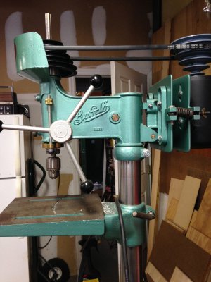
I have a comparable drill press. There is one nearly identical to mine on the vintagemachinery.com website. That one is a 1936-1939 15" model that was in a GM of Canada workshop. Mine must be a 1940 or so model and yours may be a wartime product or shortly thereafter. This is a total guess, but I worked with the successors to Buffalo to try and determine the year (+ or -) of manufacture. Including an extensive web search the only O&M manuals I can find are post WWII. My search was a while ago so perhaps some other literature is now available. The main thing with this style of 15" Buffalo drill press, is the way the head clamps to the column. A bolt through the head casting and located in front of the column squeezes the casting around the column.
Over tighten this bolt and crack goes the casting. Post war 15" models used clamps on the head behind the column, just like Delta and Atlas. My drill press came from a municipal shop and had been racked and broken. I brazed the head casting with bronze rod and machined a new bolt with a shoulder and a sleeve so that the tightening nut can only be turned within limits to prevent breaking the casting. So far, the head has not slipped on the column. I had to replace the spindle pulley because the spline was wiped out (!). I found a Harbor Freight drill press on display at the local HF store that had a pulley that looked about right, so I took down the model number and ordered one. HF was good about spares then, not so much now.

I had to machine a new spindle and a top bearing housing incorporating a double row angular contact ball bearing. I also machined out the quill at the bottom and fitted a double row angular contact ball bearing. Cutting the spline was my first attempt at that. I was lucky. The new chuck is a Rohm.

Buffalo15.jpg Buffalo15-2.jpg Buffalo15-3.jpg
 
Back
Top