BROWN & SHARPE UNIVERSAL DIVIDING HEAD

Good to see that you have made so much progress; I have seen the same condition with the wooden boxes, I think the problem is that they used hide glue, which is not waterproof; things get damp, then they fall apart with little provocation.
I too suffer with back problems; lately I bent over, messing with the cat, and it was off to the races! Two trips to the chiopracter, and occasional doses of Advil and its ALMOST back to normal, whatever that is!
 
Vacuum, the short answer is YES! Mine is a Van Norman. Only on spiral cuts will it become a challenge. Maybe that isn't an entirely accurate statement, but very few operations need the dividing head fed by the table feed. What are you planning to make?
 
I have made several projects with the "spiral index centers", as B&S calls them, spiral gears, fluted cutting tools, dividing metal rules, and a cam.
The latest project was to cut a pair of spiral gears with axes at 90 degrees, with a 2:1 ratio, these were timing gears for a "Frisco Standard" 4 HP marine engine; the interesting part is that both blanks were the same diameter, I had the original gears, which were very badly pitted, I started with the crankshaft gear, which had a rather long spiral, easy to set up as the spiral angle was about 22-1/2 degrees, so swinging the table to that angle was no problem; then came the camshaft gear, where the spiral angle was the complement of that angle, exceeding the limit of table swing, so, I had to use the universal spindle attachment and swing it in a horizontal plane to the necessary spiral angle with the table at zero.
Some may wonder how a pair of gears of 2:! ratio could be the same size OD --- so did I! the lead of the first spiral turned out to be four times that of the second gear, and when cut with the proper cutter for that number of teeth, the tooth space is wider than on a longer spiral or for that matter, a spur gear, so that the two mesh properly when assembled. For that reason, it is possible to replace spur gears with spiral gears, usually one diametral pitch coarser (I think) than the original pitch, by computing the proper spiral angle so that the gears apparent pitch diameters are the same as the original spur gears.
 
Brockwood, just got back from working out of town. I have nothing in the works yet but would like to have a idea of what I need to gather up to be able to index the Bridgeport table using the dividing head when the need arises. I never know what I will run into when the "you are our last resort" call comes in. What amazes me is how much the B&S dividing heads weigh.
 
Indexing the table with the DH is interesting. Should be straight forward though. I'm still studying spiral calculations.
Yes, these are heavyweights.
 
Yes, they are heavy, but I can still (at 73) manage it, but made a lifting rig, will post a pic soon
 
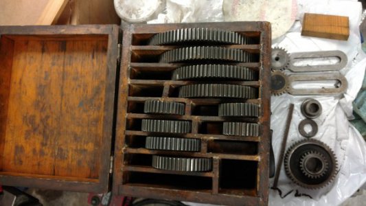
The box is back together. Extra are a correct 48 tooth gear & a 24 tooth mystery gear with a timing mark. I'm planning to at least make the missing 56 tooth gear. Between pics on the net & whomever assembled this box the last time, gear fitment & the still existing number stamps on the box no longer match. It's usable!


IMG_20180522_091710943.jpg
 
It appears that you have two idler gears, when only one is required to reverse the spiral as required, but you are missing the compounding stud; it looks similar to the idler, but has a shaft with a free running sleeve that is keyed, and the end is threaded for a nut that retains the two gears that are used on it. Also there is a shaft that fits in the dividing head in place of the center; in essence it is a center with a shaft attached that runs out the back end of the head and has a mounting for gears, and is used for differential indexing of (prime) numbers of divisions.
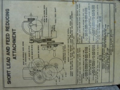
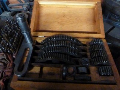
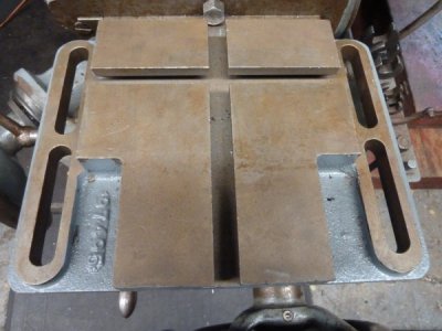
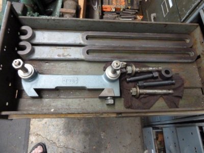
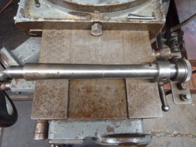
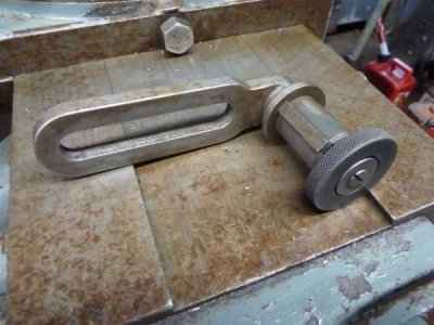
On my mill, all the gear set is within a compartment under the gearbox, which also contains the dividing plates. I am attaching pics of the compound shaft bracket, the shaft/center for differential indexing, the dividing head raising block, and the short lead and feed reducing attachment, and the arbor support braces. I have foundry patterns for the raising block, the base of the arbor support and could make drawings for the compounding bracket and the diff. index shaft. I have no idea what that compounded gear in your picture is, have not seen suchlike in any pics or parts books. You could use the extra idler bracket to make a compounding bracket, I did that for my mill.

B&S 001.JPG

B&S 002.JPG

B&S 003.JPG

B&S 004.JPG

B&S 005.JPG

B&S 006.JPG
 
The more you find out about the old B&S mills the better they are. Everyone thinks the old mills couldn't do anything but straight milling operations. Everybody wants Bridgeport ill take an ole B&S. But got to have all the extras. Yupp
 
Indexing the table with the DH is interesting. Should be straight forward though. I'm still studying spiral calculations.
Yes, these are heavyweights.
No calculations necessary, its all posted in Brown & Sharpe's book 'Practical Treatise on Milling and Milling Machines" There are tables of gearing for every possible spiral, with the gears provided; with the short lead attachment, you can mill threads; I think the attachment
The more you find out about the old B&S mills the better they are. Everyone thinks the old mills couldn't do anything but straight milling operations. Everybody wants Bridgeport ill take an ole B&S. But got to have all the extras. Yupp
I'd have to guess that the cost of "all the accessories" would cost way on the far side of what the machine cost. For mine, I also have the slotting/shaping attachment, both sizes of the toolmaker's universal vise, and the rack cutting vise and part of the rack tooth spacing fixture.
 
Back
Top