Bridgeport X & Y feed screw nut replacement ...

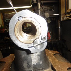
I have been replacing Bridgeport screws and nuts for 1/2 a century. The older models the nuts were split or cut like the OP's first picture. Then around 25 years ago when you ordered nuts from Bridgeport they came as a 2 piece that helped reduce the backlash on the entire thread and not the old ones that had a Philister screw bending one side in. The newer ones had 2 Bijur tubing goes to the top and bottom nut, the old ones you lined up marks on the front of the table and saddle so a set screw plug above the nuts could be removed and oil was squirted down the hole and the hole in the bracket to feed the Y nut too. But many people never knew about the set screw so the Y axis never got oil. Most squirted oil on the X axis screw only. I would never use grease on that Z axis bevel gear assembly as it will get contaminated with crud and chips and it will wear the gears 3 times as fast IMHO.

One thing too. If the ways are worn remove the pins that align the end screw brackets and with the cap screws finger tight, crank the feed screw to the extreme in position and then tighten the bracket. Then re-drill the pin holes and install spring pins. If You don't do that the close you screw the bracket to the center it will bind. Never hurts to re-engineer a machine as long as it gets better. Rich
 
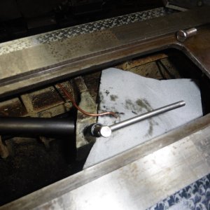
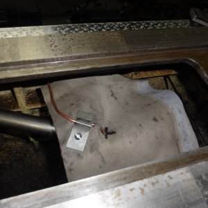
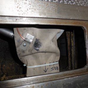
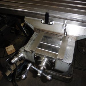
Thanks for the info Richard. If you look in the last pic above, you will see that I installed a shield above the gears to keep contaminants out. When I disassembled the machine there was a fair amount of swarf in the gear assembly and considerable backlash. I shimmed out the back lash after cleaning things up. I think with the shield in place it will be fine. The Y axis on mine had considerably more wear than the X, most likely for the reason you mentioned, and I will be adding a separate line for it when it goes back together. Mike
 
Yeah I saw the guard but I still would do it. Hey it's your machine and if it works for you, I just figure in all my years I have only seen 1 machine with bad gears. Have a great day. Rich
 
I have read, seen and heard to never use an air gun to clean out chips when milling for obvious reasons. When I saw FOMOGO's pics for the tray to protect from contaminants I was impressed. Good idea.
When I took my step pulley down far enough to inspect the bevel gear in the knee, I was surprised to see no chips. The bevel gear was dry. I can only assume who ever had this BP before me, must have performed some sort of clean up/refurbish on the lower end. Regarding grease, I will never question Mr. King's advise but I don't see any way to oil/grease the bevel gear.
How do the rest of you lubricate your bevel gear??
Thanks.
 
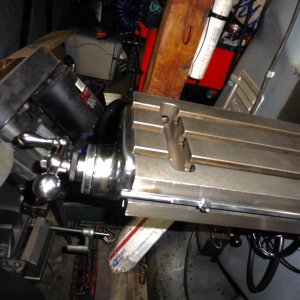
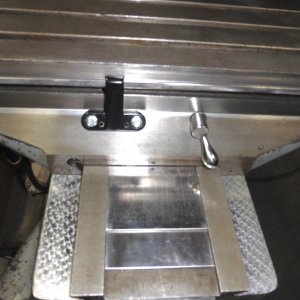
Almost finished with the lower end. I'm getting pretty good at putting this thing together, and taking it back apart, due to forgetting a piece, or changing my mind on how to go about something. When I went to install the X&Y nut, it became clear that it was going to be problematic for the metal gear cover to clear the nut when moving the Y axis, so out it came. Looked around the shop and settled on a piece of reinforced rubber sheet from the gauntlet of an old bead blast glove. Drilled and tapped a hole for a 10-24 screw and made a small clamp to hold the grease tube and rubber sheet in place in conjunction with a few of the ever popular zip ties.
P1010763.JPGP1010764.JPGP1010767.JPG
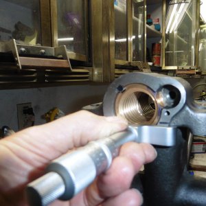
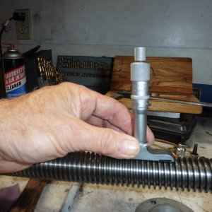
Going back a bit to the split nut issue of how to shim the two sections to get maximum screw engagement. This was established by pushing the two nut halves together and using a depth mic to measure from the outside machined surface of the casting to the end of the nut, and then threading the acme screw into the two halves of the nut until both sections of the nut were on the least worn part of the shaft, and then taking another depth measurement at the same place. This process gave me a space of .097 between the two nut halves. I searched my stash and not finding anything appropriate, I lite on the idea of trying an o-ring. I found one that measured .123 and cut it to fit the casting bore tight to both sides of the key that holds nut sections in place. After assembling the nuts, o-ring and nut adjusting screw, I used the adjusting screw to compress the o-ring to the .097 I required, and threaded the acme screw into place. I did a final adjustment to get a snug but movable fit. Installed the assembly on the mill, adjusted the Y gib for minimal side to side movement (.0003 at the outermost end of the saddle), and ended up with .0025 backlash on the most worn section of the screw, where there was originally .049 . Pretty happy overall, and learned a lot in the process. Will post some more tomorrow, time for bed. Mike


P1010760.JPGP1010758.JPGP1010759.JPG
 
Last edited:
I think you are doing a fine job. I have enjoyed your journey so far. Maybe when I retire I will follow your lead. Meanwhile my old BP does what I ask of it.
 
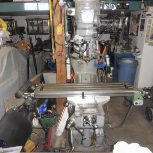
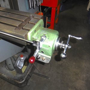
Finally pretty much got my mill back together. Still have a few things to polish up, and reinstall wipers and way covers. Ended up with zero backlash on the X axis, but it is a little tight at the extreme ends. Still movable, but tight enough that the power feed clutch will disengage at the very ends. I could pull it back down and take .015 or so off the thickness of the o-ring and I'm confident that all would be well, but I've decided to wait until I get the big lathe set up in the new shop. Then I will pull the X axis lead screw and single point it so the thread is uniform along it's entire length. Spent an hour cleaning up the X axis lock handle, the last one thankfully . It looked like it had been run through a hammer mill. A lot of nicks and gouges. Took the worst out with a file, then medium, and fine 3M Rolocs on a 90 deg die grinder, and finally emery compound on the buffer and a coat of wax. It's starting to look good enough that I just may have to break down and paint it at some point, but for now its just good to have it in service again. Mike
P1010850.jpgP1010851.jpgP1010852.jpgP1010853.jpgP1010854.jpg
 
I suspect the table is worn in the middle and bent so the outside ends are lower plus the screw is unworn on the ends. . The table is bend because they stretch when you tighten the Tee Bolts. Many call it peening. But it's a reverse peening inside the T-slots. I like what your doing but hopefully you will trust my years of experience on building new machines at the factories and rebuilding machinery for over 50 years. Did you remove the end bracket alignment pins like I mentioned before? When I assemble a Mill (Bridgeport or other brands) I leave out the pins and leave the bracket screws loose and with the gib loose so it has .0005" per side then screw the table to each end as far as the travel will let you and then tighten the end brackets and then try putting in the pins. If they are not aligned I drill them to the next size and put in new ones. If you had a straight-edge I would bet money the table top is high in middle of convex (bent) and that means the bottom is bent too. That contributes to the ends getting tight too. I come on the forums to help and teach.

I have written this 2 times as separate posts, but it doesn't show up.....but disconnect both ends and try pushing the table by hand end to end. That would tell you if its the screw or table. Rich
 
Last edited:
Thanks for the input Richard, always looking for the best way to go about things, and I will certainly check into that the next I take it back down to cut the lead screw. Thanks, Mike
 
Back
Top